
HALL EFFECT SWITCHES
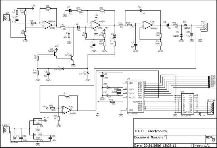
The Hall-effect switch operates on the principle of detecting magnetic fields and can be utilized in various applications such as position sensing, speed detection, and proximity sensing. The basic configuration of a Hall-effect switch consists of a Hall sensor, which generates a voltage proportional to the magnetic field strength, and an amplifier to enhance the signal.
In the circuit design, the Hall-effect sensor is connected to an operational amplifier that boosts the output signal for better readability and processing. The output of the amplifier can be connected to a microcontroller or a digital signal processor, which interprets the signal and performs the necessary actions based on predefined thresholds.
The innovative circuit design reduces the total number of wires required by employing a multiplexing technique or a shared communication bus, allowing multiple Hall-effect switches to communicate over a single set of wires. This not only simplifies the wiring but also minimizes the overall size and complexity of the system.
For instance, in a configuration with multiple Hall-effect switches, each switch can be addressed sequentially, with the microcontroller activating one switch at a time and reading its output before moving to the next. This approach maintains the integrity of the signals while significantly decreasing the wiring requirements, making it ideal for applications in robotics, automotive systems, and industrial automation where space and weight are critical factors.
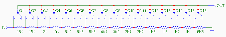
Overall, the advantages of Hall-effect switches, combined with the innovative circuit design that reduces wiring complexity, make this solution highly efficient and suitable for a wide range of electronic applications.Hall-effect switches have several advantages over mechanical and optically coupled switches. They`re insensitive to environmental light and dirt, they don`t bind, and they don`t sustain mechanical wear. Their major drawback is that they require three wires per device. The circuit shown, however, reduces this wire count to N + 1 wires for N devices.Amplifier.. 🔗 External reference
Related Circuits
The traditional potentiometer is implemented with an electrical contact that slides over a resistive layer. An example of a well-known audio-grade potmeter is the Alps Blue. A high-end (good and costly) alternative is the rotary switch. This device consists...
It can drive up to 128 individual relays, solenoids, motors, fireworks, pyrophones, etc. With a MIDI note-on message you may switch on one of the 128 LEDs (or relays). Outputs may be switched off by sending a note-off message,...
This amplifier is designed for outdoor installation and is connected to an indoor power line box. It utilizes either 50-ohm or 75-ohm coaxial cables for the connection between indoor and outdoor units. The amplifier circuit board is depicted in...
This is an early picture of my discolight effect. Because of the AGC circuit, there's no need for potentiometers for sensitivity adjustment. I replaced them with trimmers. Now the microphone is on the control electronics because there's no need...
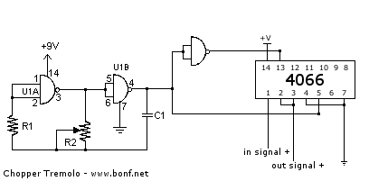
A tremolo is an effect unit that modulates the amplitude of the guitar signal, typically using a triangular waveform. This particular version employs a square waveform, resulting in a more abrupt, chopping effect. Such effects are prominently featured in...
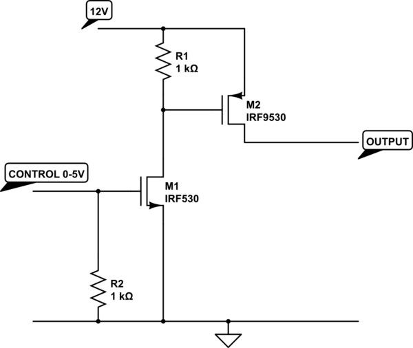
The transistor depicted is a P-channel MOSFET functioning as a high-side switch. Typically, an N-channel MOSFET is preferred for low-side switching, but the P-channel variant can be utilized effectively with the addition of a load at the drain. When...