
switches MOSFET as a switch

The described circuit utilizing a P-channel MOSFET as a high-side switch operates under the principle of controlling the voltage applied to the gate terminal. The gate is responsible for regulating the conductive state of the MOSFET, which in turn affects the load connected to the drain. A pull-up resistor connected to the gate ensures that the MOSFET remains off when the control signal is not actively driving it, thus preventing unintended activation.
In practical applications, the P-channel MOSFET is connected to the positive supply voltage (VDD), with the load connected between the drain and ground. When the control signal is low, the gate-source voltage (Vgs) becomes negative, allowing the MOSFET to enter saturation and conduct current to the load. The load will receive the full supply voltage, enabling it to operate as intended.
The importance of the pull-down resistor in the N-channel MOSFET configuration cannot be understated. It serves to ensure that the gate is pulled to ground when the control signal is not present, thereby keeping the MOSFET in the off state. This configuration is particularly beneficial in applications where the control signal may be subject to noise or fluctuations, as it provides a reliable means of preventing false triggering.
Understanding the gate threshold voltage is critical when designing circuits with MOSFETs. The threshold voltage is the minimum gate-source voltage required to initiate conduction. Logic-level MOSFETs are designed to operate effectively at lower control voltages, making them suitable for interfacing with microcontrollers and digital logic circuits.
In conclusion, the use of P-channel and N-channel MOSFETs in high-side and low-side switching applications, respectively, provides flexibility in circuit design. Proper implementation of gate control strategies, including the use of pull-up and pull-down resistors, ensures reliable operation and enhances the robustness of the circuit against undefined states.The transistor shown is a P-channel MOSFET acting as a "high-side switch". More commonly, an N-channel MOSFET low-side switch is used, but what you have will work as long once you add something to the drain such as in this image of P-Channel MOSFET switch from : When the control goes "HI" the MOSFET switch is "OFF. " When the control goes "LO" the MOSFET acts as a switch, essentially shorting the drain and source. While this is not entirely true, it is a close approximation as long as the transistor is fully saturated. So the schematic you have shown can be used to switch 12V to something, but it will not connect the output to 0V unless a pull down resistor is used as shown in the above image.
The opposite control scenario works for an N-channel MOSFET: LO control turns the switch off, HI control turns the switch ON. However, an N-channel is more suited to be a "LO-side switch" connecting the output to ground instead of VDD as in this image of an N-Channel MOSFET switch: The actual voltage level that determines if the FET is on or off is known as the gate threshold voltage.
So called "logic level gates" work at lower voltages common in digital circuits such as 1. 8V, 3. 3V, or 5V. Although, crossing this threshold does not entirely turn the switch on or off, it merely allows the FET to start or stop conducting. The FET should be full saturated with the values noted in the datasheet to full turn ON or OFF. I should also add that it is pretty common practice to include a pull up resistor (10k or so) at the gate of the P-Channel MOSFET to keep it OFF in unknown states.
Similarily, a pull down resistor is used at the gate of the N-Channel MOSFET to keep it OFF in unknown states. 🔗 External reference
Related Circuits
This amplifier is designed to be as flexible as possible, with no bad habits. Indeed, it will operate stably with supply voltages as low as +/-5V (completely pointless, but interesting), all the way to the maximum supply voltage of...
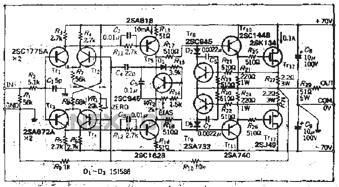
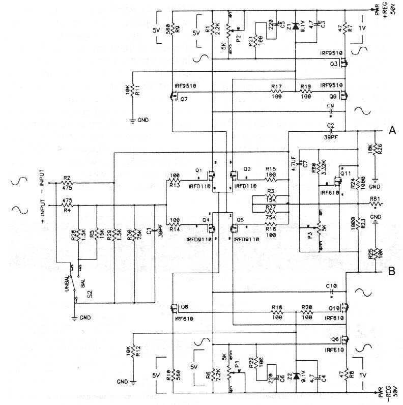
The south circuit consists of four parts, arranged in descending order: an NPN transistor dynamic garbage device (T1), a PNP transistor differential amplifier (T2, T3) forming a double differential circuit, two balanced output amplifiers with opposite phase, and a...
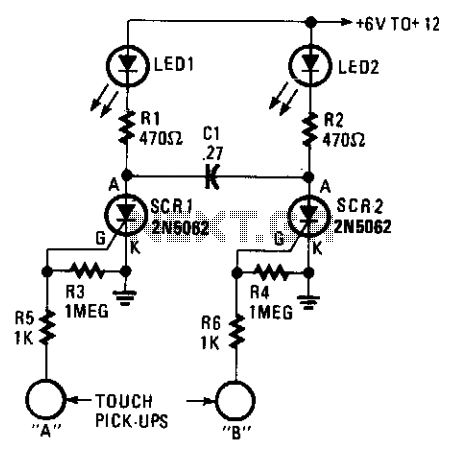
A touch on/off switch circuit is designed using two interconnected sensitive gate SCRs. When one SCR is activated, it forces the other SCR to turn off, creating a toggling effect that allows for an on/off condition for each of...
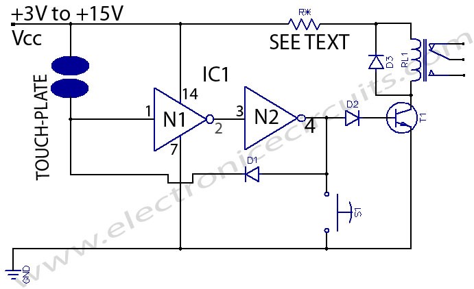
This is a touch switch designed to control LEDs, relays, and similar devices through a buffer transistor stage. It can be constructed using any CMOS inverter chip. The touch switch circuit operates by utilizing the capacitive touch sensing principle, which...
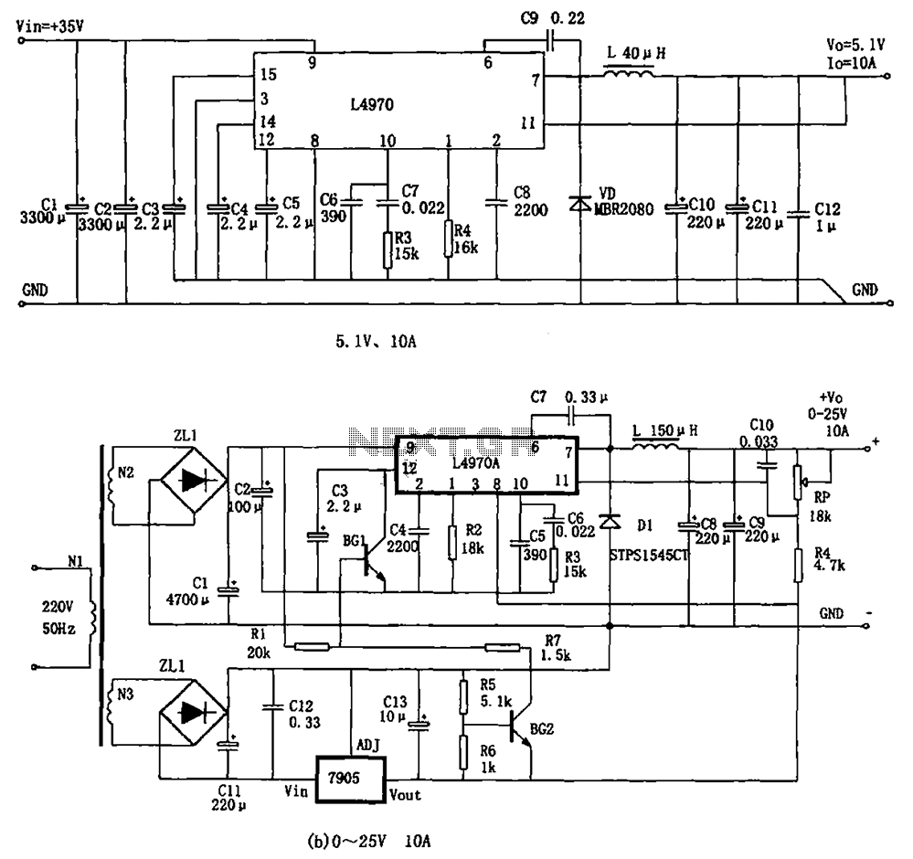
The L4970A power switching supply is a high-power monolithic integrated switching regulator, packaged in a SIP-15 format. It has specific characteristics: (1) The input voltage must be at least 11V, typically ranging from 15V to 40V; (2) The output...
The MOSFETS we are dealing with are three terminal devices which are used to control electron flow in a circuit. Two of the pins (the source and drain) pass the current, and the third pin (the gate) is used...