
simple circuit willing to pay for full design!
The circuit in question appears to involve fundamental electronic components, which may include resistors, capacitors, diodes, transistors, and integrated circuits. Each of these components plays a crucial role in the overall functionality of a circuit.
Resistors are used to limit current flow and divide voltages, while capacitors store and release electrical energy, often used for filtering or smoothing signals. Diodes allow current to flow in one direction only, serving as protective elements against reverse polarity. Transistors serve as switches or amplifiers, controlling the flow of current based on input signals. Integrated circuits (ICs) can encapsulate multiple functions into a single package, providing advanced capabilities such as logic processing or signal modulation.
To create a basic electronic schematic, one would typically start by identifying the power source, which could be a battery or a power supply. The components would then be connected using conductive paths, represented by lines on the schematic. It is essential to ensure that the polarity of components such as diodes and electrolytic capacitors is correctly oriented to avoid circuit failure.
The arrangement of components should be logical, following the intended function of the circuit. For example, in a simple LED circuit, a resistor would be placed in series with the LED to limit current, and a power source would be connected to the circuit. The schematic would clearly show the connections, with appropriate labels for each component to facilitate understanding and troubleshooting.
Overall, a well-designed schematic serves as a blueprint for constructing the physical circuit, allowing for effective assembly, testing, and modification as needed.Hi everyone, A bit of background first, I know only the basics of electronics (ie: I know what components do and how to read schematics), but have no.. 🔗 External reference
Related Circuits
The input signal is applied to a gate G and then to a counter for a precise period of time. After this period, the input signal is stopped for a while, and then the cycle is repeated. During the...
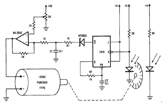
A simple encoder circuit for a DC motor can be constructed using this circuit diagram. The system consists of the HA-2542, a small 12-V DC motor, and a position encoder. During operation, the encoder generates a series of constant-width...
This room light controller project automatically uses a microcontroller to manage a visitor counter, providing a reliable circuit for controlling the room lighting. The room light controller circuit integrates a microcontroller that processes inputs from a visitor counter. This setup...
The circuit has been designed for telephone apparatus to indicate an incoming call as it rings using an LED for visual indication. BC550, an NPN general-purpose transistor, is utilized in the design. The circuit operates by detecting the ringing voltage...
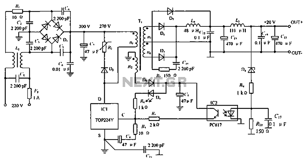
The circuit depicted in the figure is designed to achieve a higher power output by modifying specific components. On the left side of the figure, components R1, L1, D1, and capacitors C1 to C7 form a conventional filtering and...
A circuit is being designed to operate based on car locks, which receive a negative pulse to activate a latched relay, powering the ACC line that connects to a startup/shutdown controller. The current circuit configuration presents a challenge; to...