
HAM Modulation Monitor
L1 - 23 Turns 24 SWG
Wound over 1.5Cm
dia PVC tube
C1 - 2J PVC Gang Capacitor
D1 - IN34 or IN4148
C2 - 0.01 ceramic disc
EP - 1 K OHMS Headphone
The Modulation Monitor circuit is designed to enable amateur radio operators (hams) to assess the quality of their transmissions without requiring a direct connection to the transmitter. This feature is particularly advantageous for ensuring optimal performance while maintaining the integrity of the transmitted signal. The circuit primarily consists of an inductor (L1), a gang capacitor (C1), a diode (D1), a ceramic capacitor (C2), and a headphone output (EP).
L1 is constructed using 23 turns of 24 SWG wire wound around a 1.5 cm diameter PVC tube, which serves as the inductor. This component is crucial for tuning into the desired frequency range, specifically the 7 MHz ham band, although it can be adjusted for other bands by modifying the values of L1 and C1. The gang capacitor C1, rated at 2J, allows for fine-tuning of the circuit's resonance, enhancing the clarity of the audio signal received through the headphones.
D1 can be either an IN34 or IN4148 diode, which plays a vital role in rectifying the incoming RF signal to audio frequencies that can be processed by the headphones. The inclusion of C2, a 0.01µF ceramic disc capacitor, aids in filtering and stabilizing the signal, ensuring that the audio output remains clean and free of unwanted noise.
For headphone connectivity, the circuit is designed to work with 1K ohm impedance headphones. However, if low impedance headphones are preferred, it is recommended to connect a suitable length of wire from the junction between the diode and the coil through a 1000pF capacitor to adapt the circuit accordingly.
The entire assembly can be conveniently housed in a plastic enclosure, allowing for easy placement near the transmitter. Proper adjustment of the gang capacitor C1 is essential to achieve maximum audio output, enabling the operator to monitor their transmission quality effectively. This simple yet effective circuit provides a valuable tool for amateur radio enthusiasts, ensuring that their communications are clear and reliable.Modulation Monitor is a simple and useful circuit for hams. You can listen to on air transmission from your rig and be sure about the quality of the transmission. It requires no direct connection with the transmitter. In the prototype, headphones of 1K impedance are used. If you want to use ordinary low impedance head phones, connect a suitable length of wire from the junction between the diode and the coil through a 1000pf capacitor.
L1 is easily available from junk box of hams since it the same as that used by hams in their QRP Transmitter. The entire setup can be housed inside a plastic box and placed near your transmitter adjust gang condenser C1 for maximum sound. The circuit is for 7 MHz ham band. Suitably changing the values of L1 and C1, it can be used for other ham bands also. L1 - 23 Turns 24 SWG Wound over 1.5Cm dia PVC tube C1 - 2J PVC Gang Capacitor D1 - IN34 or IN4148 C2 - 0.01 ceramic disc EP - 1 K OHMS Headphone
🔗 External reference
Related Circuits
When the circuit is connected to hi-fi equipment or at both ends of the electronic instrument's speaker, the audio level can be modulated to a 500W lamp proportionally. This is achieved using three appropriate sets of audio filters and...
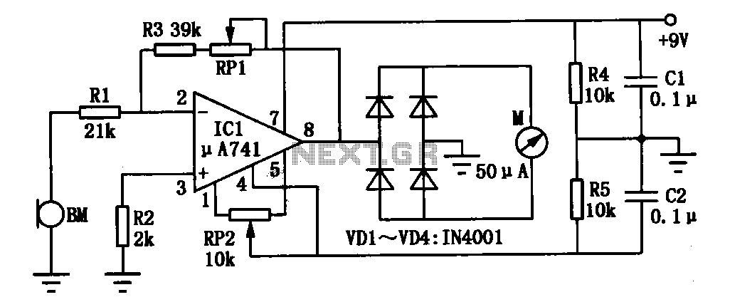
An environmental noise monitor circuit is presented. It primarily consists of a high-gain operational amplifier configured to amplify noise signals. The measured noise signal is displayed on an ammeter. The operational amplifier (IC1) receives the noise signal detected by...
This application note describes the creation of a heart rate monitor utilizing an infrared (IR) LED and a phototransistor pair, with the waveform observed at the output of the phototransistor. The purpose of this project is to demonstrate a...
Figure A illustrates the circuit of a direct-trigger timing light. The trigger voltage is obtained from the vehicle's ignition circuit via a direct connection to a spark plug. Figure B depicts a circuit utilizing an inductive pickup. A trigger...
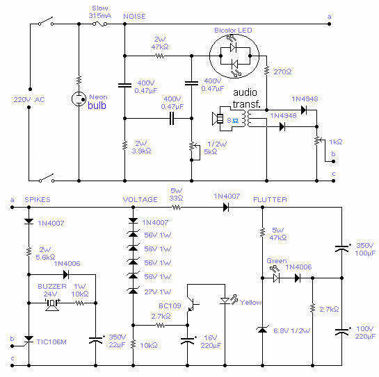
With this circuit you will be able to monitor the quality of the mains. There are 4 distinct sections, each supervising a parameter pertinent to the quality of the supply line. The noise section consists of a 50Hz filter...
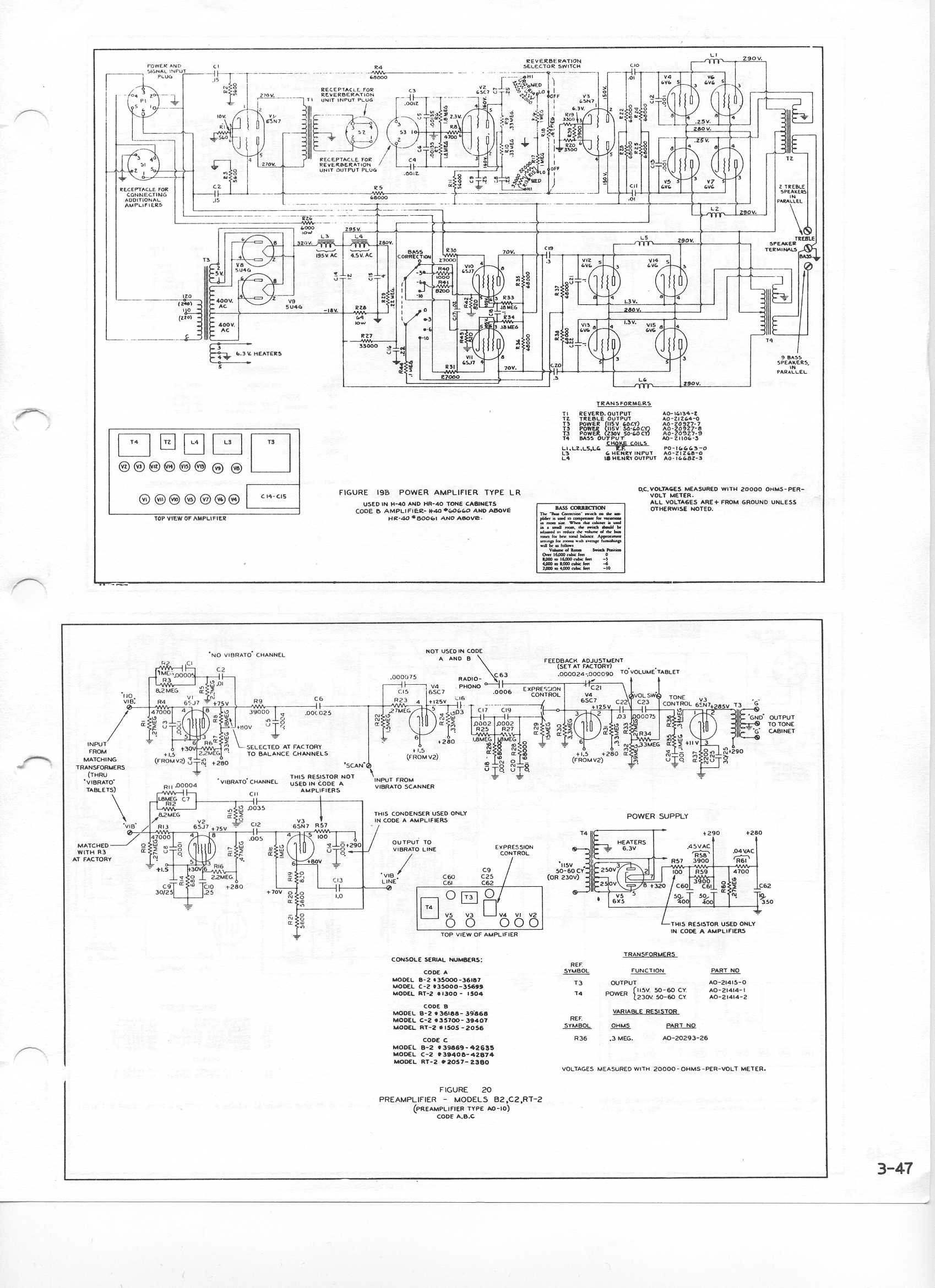
During a practice session on a Hammond C2 organ, the sound unexpectedly diminishes and becomes soft to the point of being inaudible. The Hammond C2 organ is an electromechanical instrument that utilizes a unique tonewheel generator system to produce sound....