
Environmental Noise Monitor
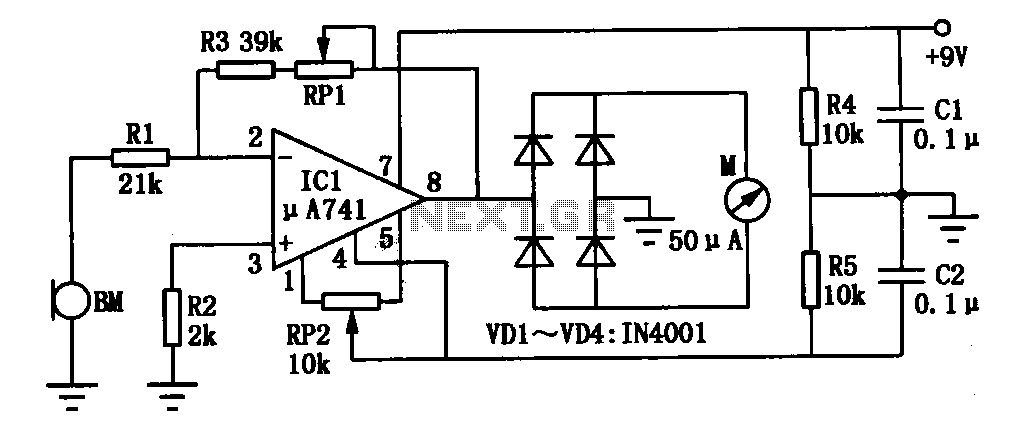
The environmental noise monitor circuit is designed to accurately measure ambient noise levels through a systematic approach involving several key components. The circuit utilizes a high-gain operational amplifier (IC1) to amplify the electrical signal generated by the microphone (BM) in response to environmental noise. This configuration allows for the detection of low-level noise signals that may otherwise be imperceptible.
The microphone converts sound waves into an electrical signal, which is fed into the inverting input of the operational amplifier. The gain of the amplifier is crucial for enhancing the signal-to-noise ratio, ensuring that the ambient noise is effectively captured and processed. Following the amplification stage, the signal undergoes full-wave rectification through a series of diodes (VD1 to VD4). This rectification process converts the alternating current (AC) signal into a direct current (DC) signal, allowing for a more straightforward measurement of the noise intensity.
The ammeter serves as the final output device, providing a visual representation of the noise level. The circuit includes two potentiometers for calibration and sensitivity adjustment. The zero potentiometer (RP2) is used to ensure that the ammeter reads zero in the absence of noise, facilitating accurate measurements. The sensitivity potentiometer (RP1) allows for fine-tuning of the ammeter response, enabling the user to calibrate the circuit according to specific noise level standards.
Overall, this environmental noise monitor circuit is a robust design that effectively captures and displays noise levels, making it suitable for a variety of applications, including environmental monitoring and sound level assessment in various settings. The combination of high-gain amplification, rectification, and adjustable calibration ensures reliable performance and accuracy in measuring ambient noise.Environmental noise monitor circuit is shown. It mainly consists of high gain mu Specification for Zinc composition. Measured noise signal is indicated by the ammeter. ICl oper ational amplifier connected as amplifier noise, the noise signal to be detected by the microphone BM applied to the inverting input of ICl, zoom in and then full-wave rectification by the diode VDl ~ VD4, last ammeter deflection, thereby indicating the intensity of the ambient noise. When adjusted, the short ends of the first microphone, adjust the zero potentiometer RP2, ammeter indicates 0.
Adjustment potentiometer RPl, can change the sensitivity of the ammeter. Corresponding to the intensity of the noise meter scale values available a standard to monitor calibration.
Related Circuits
This circuit is designed to indicate, via a flashing LED, when room noise exceeds a predetermined threshold, which can be set to one of three fixed levels: 50, 70, or 85 dB. Two operational amplifiers (op-amps) are utilized to...
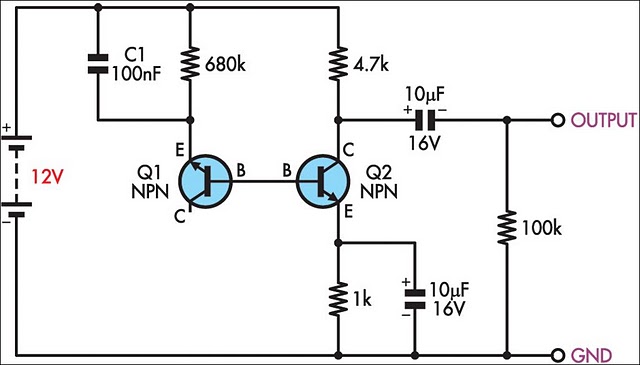
This two-transistor white noise generator exhibits approximately 30 dB more noise than traditional designs. Transistors Q1 and Q2 can be any small-signal transistors with a beta rating of up to 400. The reverse-biased emitter-base junction of Q1 serves as...
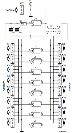
Receiver interference is a common issue among model builders. Preventive measures, such as ferrite beads fitted to servo cables, are frequently employed in larger models and electrically driven models to prevent the cables from acting as antennas and radiating...
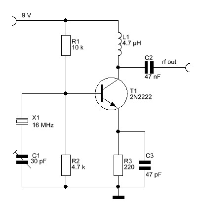
The overall performance of any RF circuit regarding its phase noise and spectral purity depends significantly on the frequency-generating circuitry, commonly an oscillator. Low noise oscillators with high spectral purity are neither mysterious nor magical. Many individuals perceive the...
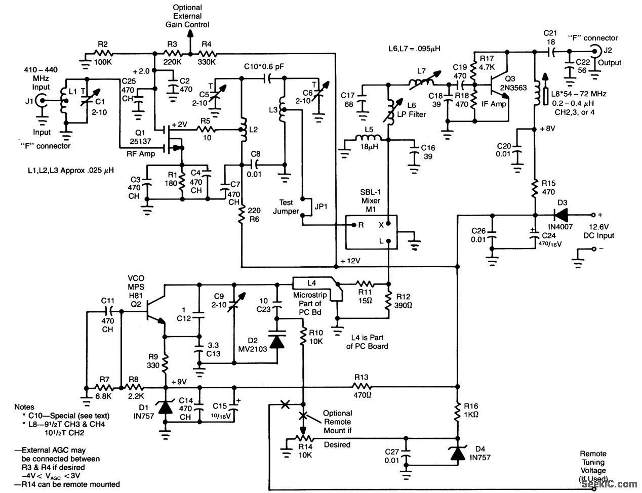
L1, Q1, L2, and L3 form an RF amplifier stage that drives M1, a doubly balanced mixer. Q4 serves as a local oscillator stage operating in the 375-MHz range. Signals in the 420 to 450-MHz range from Q1 are...
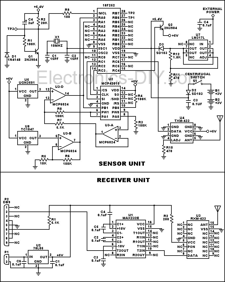
This device is designed to measure the torque in an automobile drive shaft and provide output to a vehicle data recording system or a portable computer via an RS-232 interface. The received data can then be combined with RPM...