
220V Mains Quality Monitor
The circuit is designed to monitor various parameters of mains quality, providing both auditory and visual feedback. It is divided into four primary sections, each responsible for assessing a specific aspect of the mains supply.
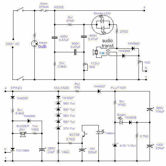
The first section focuses on noise detection and incorporates a 50Hz low-pass filter along with a speaker. This arrangement allows the user to hear any noise present in the mains supply. A bicolor LED, adjustable via a 5k potentiometer, provides a visual representation of noise levels or waveform asymmetry. The adjustment of the potentiometer is crucial for calibrating the LED to indicate minimal light in normal operating conditions.
The second section is dedicated to spike detection. It is designed to identify voltage spikes that may occur on the mains line. A potentiometer is included to set the sensitivity of the detection circuit, ensuring that it does not trigger false alarms during routine operations, such as switching on lights. However, it remains sensitive enough to detect nearby switching operations.
In the third section, the circuit monitors the actual mains voltage. A yellow LED is employed to indicate voltage levels, blinking at a frequency of 6 Hz under normal conditions. If a 10% increase in voltage is detected, the blinking rate increases to 12 Hz, while a 10% decrease in voltage causes the LED to stop blinking altogether. This provides an immediate visual reference for voltage stability.
The final section of the circuit is responsible for monitoring slow variations or 'flutter' in the mains voltage. This aspect is critical for assessing the overall stability of the supply.
For operation with a 220V mains supply, the circuit is appropriately configured. However, for a 230V supply, modifications are necessary: the 27V zener diode should be replaced with a 39V component, and for 60Hz operation, the resistor values must be adjusted from 3.9k to 3.3k and from 47k to 39k. It is noted that adapting the circuit for 110V operation would require significant redesign and has not been attempted.With this circuit you will be able to monitor the quality of the mains. There are 4 distinct sections, each supervising a parameter pertinent to the quality of the supply line. The noise section consists of a 50Hz filter and a speaker where you will hear the noise present on the line.
The bicolor LED should be adjusted for the least light with the 5k pot and gives a visual indication of noise or asymmetry in the wave. The second section will detect any spike which is overimposed on the mains voltage: adjust the pot so that it will not trip if you just switch on the light, sensitivity is high enough to detect a switching operation from a close neighbor.
The buzzer will beep for about 1sec anytime there is a spike. The actual voltage is detected with section 3: the yellow led will blink at a rate of 6 Hz but will visibly double to 12 Hz for a 10% increase or will come to a halt for a 10% decrease of the voltage. The last section will show the flutter or slow variations of the mains voltage. The circuit will work for a 220V mains: for 230V operation, change the 27V zener to 39V and for 60Hz operation change the 3.9k resistor to 3.3k and the 47k resistor to 39k.
Operation at 110V will call for a major redesign of the component values and has not been attempted. 🔗 External reference
Related Circuits
This simple circuit allows for the monitoring of one's heartbeat, particularly useful during exercise. The transducer employed for pulse detection is an electronic component. This circuit typically incorporates a photoplethysmogram (PPG) sensor as the transducer to detect changes in blood...

This DIY 12V to 220V DC to AC converter utilizes a CMOS 4047 as its main component, effectively transforming 12V DC into 220V AC. The circuit design of this DC to AC converter primarily revolves around the CMOS 4047 integrated...
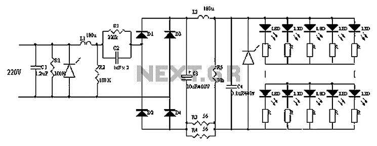
Circuits C1, R1, varistors, L1, and R2 form a filter circuit that includes a primary power supply capable of filtering out transient overvoltage inputs. The circuit also consists of C2 and R2, with additional components C3, C4, and L2....

A power inverter converts direct current (DC) power to standard alternating current (AC) power. The following schematic illustrates a 12V power inverter circuit diagram. The 12V power inverter circuit typically consists of several key components that work together to achieve...
The monitor detects an open door, and if the condition is not rectified within 20 seconds, it triggers a beeping alarm. The circuit operates using a magnetic reed switch and a magnet positioned on the door. When the door...
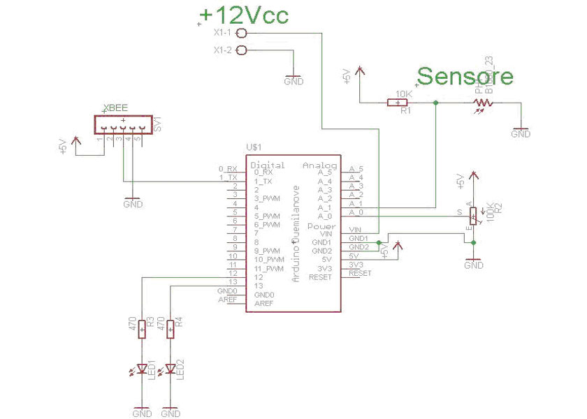
The system consists of two components: an Arduino board that detects LED pulses and transmits the data via an XBee module, and a PC that receives the data through a USB/XBee module and processes it using LabVIEW, allowing for...
Warning: include(partials/cookie-banner.php): Failed to open stream: Permission denied in /var/www/html/nextgr/view-circuit.php on line 713
Warning: include(): Failed opening 'partials/cookie-banner.php' for inclusion (include_path='.:/usr/share/php') in /var/www/html/nextgr/view-circuit.php on line 713