
Handy Bright Light Circuit
The LT1932 integrated circuit is a highly efficient step-up converter specifically designed for LED applications. Its ability to regulate current makes it an ideal choice for driving LEDs, which require a consistent current for optimal brightness. The circuit's design allows for flexibility in powering multiple LEDs or a single LED, accommodating various user needs. The choice of components, such as the Schottky diode and low ESR capacitor, is crucial for maintaining efficiency and performance. The use of a ferrite core inductor enhances the circuit's ability to handle high-frequency operations while minimizing losses.
When constructing the circuit, it is important to follow best practices in PCB design to ensure stability and performance. This includes maintaining short trace lengths for high-frequency signals and providing a solid ground plane to reduce noise. Proper placement of components can further enhance performance and reliability. The circuit's versatility allows it to be adapted for different lighting applications, making it a valuable project for electronics enthusiasts and professionals alike.An interesting circuit of a true-portable and cute solid-state bright light built with LT1932. The light can be operated from two AA size dry/rechargeable pen-light cells. There is no housing included so that you can use your own imagination as to what you would like to do with this light circuit. A search light, cupboard light, pathway li ght or an inspection head light! The LED Bright Light circuit is realised using a small 6 pin integrated circuit in SMD package LT1932 (IC1) from Linear Technologies. The LT1932 is a fixed frequency step-up DC to DC converter designed to operate as a constant-current source.
Because it directly regulates output current, the LT1932 is ideal for driving light emitting diodes (LEDs) whose light intensity is proportional to the current passing through them, not the voltage across their terminals. The LT1932 accurately regulates LED current even when the input voltage is higher than the LED voltage, greatly simplifying battery powered designs.
A single external resistor sets LED current between 5mA and 40mA. In this circuit the LED current is set to 15mA with R1=1. 5Kilo Ohm. Here IC1 is configured as a two cell driver for three white LEDs(D2-D4). This design strictly follows the LT application data of LT1932. A small SMD prototyping board may be used for construction of the whole circuit. As with all switching regulators, careful attention must be paid to the PCB board layout and SMD component placement. To prevent radiation and high frequency resonance problems, proper layout of the high frequency switching path is essential.
Minimize the length and area of all traces connected to pin 1, and always use a ground plane under the switching regulator to minimize interplane coupling. The signal path including pin 1, output diode D1 and output capacitor C2, contains nanosecond rise and fall times and should be kept as short as possible.
In addition, the ground connection for the resistor R1 should be tied directly to pin 2 and not be shared with any other component, ensuring a clean, noise-free connection. Low ESR (equivalent series resistance) capacitor should be used as C2 to minimize the output ripple voltage.
Similarly, D1 must be a Schottky diode, with low forward voltage drop and fast switching speed. Make sure that the diode has a voltage rating greater than the output voltage. MBR0540 (500mA/40V) is a good selection for D1. The value and type of the power inductor (L1) also plays an important role in the overall system efficiency. As core losses at 1. 2MHz are much lower for ferrite cores than for the cheaper powdered-iron ones, ferrite core inductor should be used to obtain the best efficiency.
Choose a 4. 7 micro-henry inductor that can handle at least 500mA. Lab Note: If you wish to use only one LED at the output, Just connect its anode to the cathode terminal of D1 and its cathode terminal to pin 3 of IC1. No additions/deletions required! 🔗 External reference
Related Circuits
Adjustable 1.5 - 35 V DC Regulated Power Supply Circuit Diagram. This diagram includes three circuit designs and is categorized under Power Supply. For more information, refer to the detailed post titled "Adjustable 1.5 - 35 V DC Regulated...
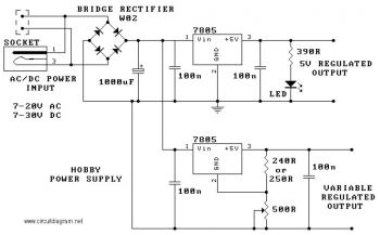
The circuit utilizes the 7805 voltage regulator, which features three connections: input, output, and ground. It delivers a fixed output voltage, with the last two digits of the part number indicating the specific output voltage, such as 05, 06,...
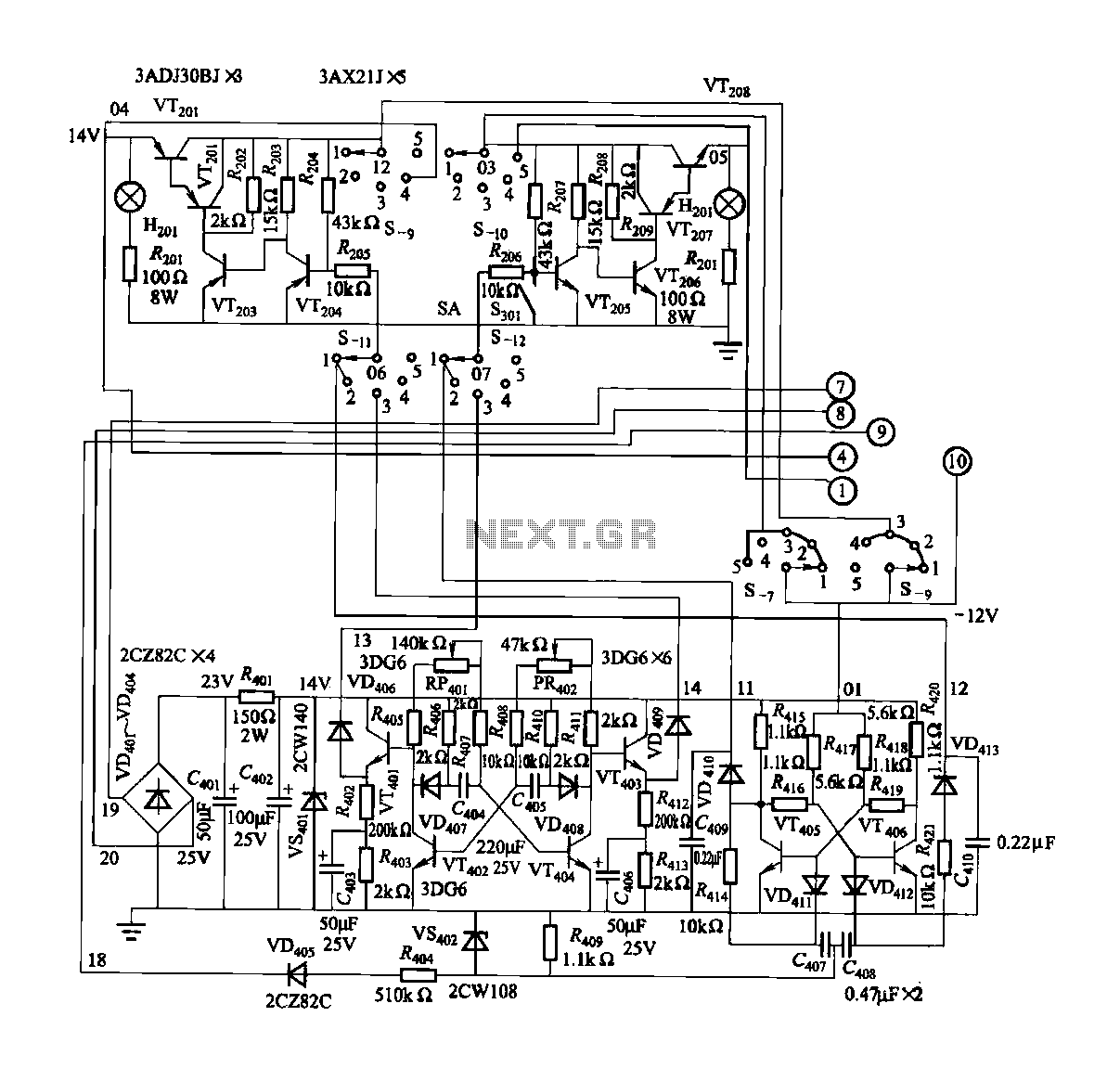
FGDF-3 is a three-phase low-temperature iron plating power commutation control switch and electronic circuit. The KGDF-3 serves as a low-temperature iron plating power supply device, incorporating the characteristics of a single-phase low-temperature iron plating power supply. This design facilitates...
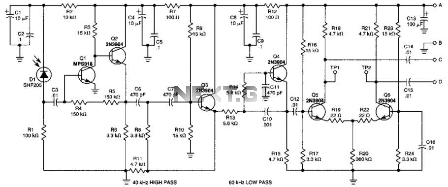
This receiver is designed to detect infrared (IR) or light beams that are frequency modulated on a 50-kHz carrier. The transistors Q2, Q1, Q3, and Q4 form an active filter and amplifier, while the differential amplifier formed by Q5...
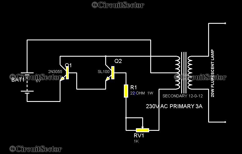
This is a straightforward circuit for an emergency light that can be assembled with relative ease. The components include two transistors, a transformer, a 20 Watt fluorescent tube, a 6V battery, and several resistors and potentiometers. The transformer in...
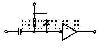
A single pulse signal generating circuit is depicted, which utilizes switch contacts to create a digital signal for reset or stop functions. This one-shot pulse generating circuit operates as a non-synchronous differential circuit. The single pulse signal generating circuit, commonly...
Warning: include(partials/cookie-banner.php): Failed to open stream: Permission denied in /var/www/html/nextgr/view-circuit.php on line 713
Warning: include(): Failed opening 'partials/cookie-banner.php' for inclusion (include_path='.:/usr/share/php') in /var/www/html/nextgr/view-circuit.php on line 713