
Fm Light Beam Receiver Circuit
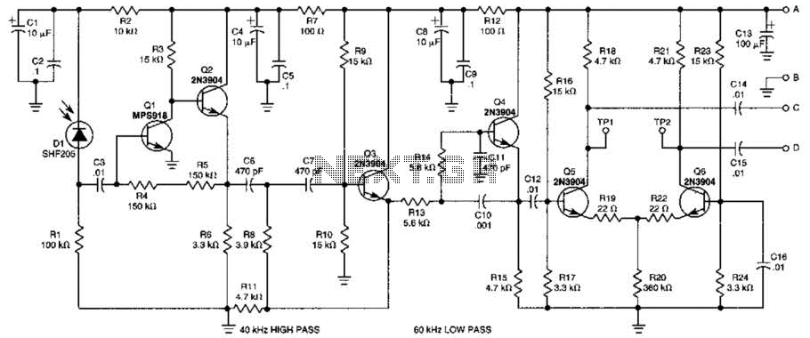
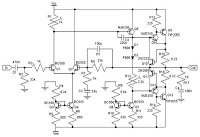
The described receiver circuit utilizes a combination of active components to effectively process modulated signals. The initial stage consists of transistors Q2, Q1, Q3, and Q4, which are configured as an active filter and amplifier. This configuration is essential for filtering out unwanted noise and amplifying the desired signal. The choice of a 50-kHz carrier frequency allows for efficient modulation and demodulation of the IR or light signals, making it suitable for various applications, such as remote controls or wireless data transmission.
Following the active filter stage, the differential amplifier formed by transistors Q5 and Q6 plays a crucial role in further enhancing the signal. Differential amplifiers are known for their ability to reject common-mode noise, which is particularly beneficial in environments with significant electromagnetic interference. By amplifying the difference between the two input signals, Q5 and Q6 ensure that the output maintains the integrity of the modulated information while increasing the overall gain of the circuit.
In summary, this receiver circuit is adept at capturing and processing frequency-modulated light signals, utilizing a well-structured combination of active filtering and differential amplification to achieve high fidelity and noise resilience in the output. The design is tailored to optimize performance for applications requiring reliable signal detection in the presence of potential noise sources. This receiver will pick lip IR or light beams that are frequency modulated on a 50-kHz carrier. Q2/Q1/Q3/Q4 from an active filter and amplifier and differential amp Q5/Q6 provide more gain. 🔗 External reference
Related Circuits
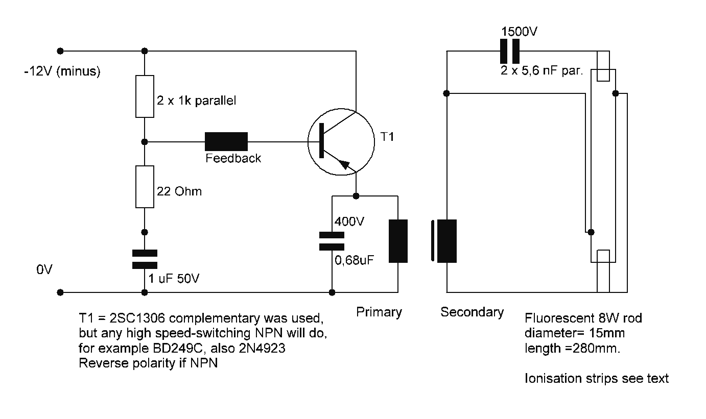
Starting a fluorescent lamp on an inverter can be challenging due to the trade-offs involved in achieving optimal operating efficiency with 12V drivers. Fluorescent lamps require a specific starting voltage to ionize the gas within the tube and initiate the...
This circuit is a simple air flow detector that signals the presence of air flow. The sensor utilized is a filament incandescent lamp. Components include an air flow detector, a sensor, an LED, and an LM339 operational amplifier. The air...
The PPI-8255 is a general-purpose I/O programmable interface that is typically connected directly to a computer bus. This article demonstrates that the card can serve dual purposes: as an expander port and for direct I/O functionality. The card can...
To configure the amplifier, set resistor R1 to its maximum value and resistor R12 to zero. After this adjustment, power on the amplifier. Adjust R1 until the measured output offset is between 30 mV and 100 mV. Once this...
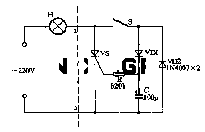
Closing the switch S allows the AC positive half-cycle to flow through diode VDI and resistor R, causing the SCR to open simultaneously at both ends of the capacitor C, which becomes fully charged. During this phase, the positive...
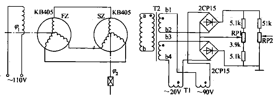
The transmitter (FZ) winding and receiver (SZ) correspond to the three-phase windings connected to a 110V AC voltage supply for transmission. The field winding, early start angle, and receiver output voltage at both ends of the stator windings reflect...
Warning: include(partials/cookie-banner.php): Failed to open stream: Permission denied in /var/www/html/nextgr/view-circuit.php on line 713
Warning: include(): Failed opening 'partials/cookie-banner.php' for inclusion (include_path='.:/usr/share/php') in /var/www/html/nextgr/view-circuit.php on line 713