
hardware aspects of moving message
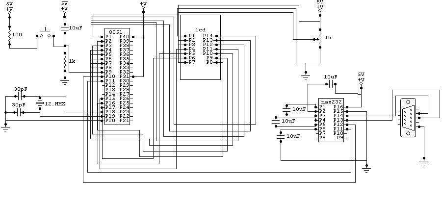
The moving message display system utilizes an LCD to present dynamic text, controlled by a microcontroller that interfaces with a computer via an RS232 serial connection. The microcontroller is programmed to manage an 8-bit data bus that connects to the LCD, allowing for efficient data transfer. The control signals generated by the microcontroller, specifically the enable, read/write, and instruction/data signals, are crucial for the operation of the LCD.
The enable signal is essential for indicating the readiness of the LCD to receive data. When the microcontroller sets this signal from high to low, the LCD captures the data present on its data lines. It is critical that the data is stable and latched before this transition occurs to ensure accurate reading. The read/write signal determines the operation mode of the LCD, allowing the microcontroller to either read from or write to the display's memory. The instruction/data line further clarifies the type of data being sent, guiding the LCD in processing the incoming information appropriately.
In practical terms, the microcontroller must monitor the busy flag of the LCD after each command to ensure that it is ready for the next operation. This is accomplished by switching the LCD into read mode and checking the status of the busy flag on the data lines. The timing diagram serves as a reference for understanding the sequence of operations and ensuring synchronization between the microcontroller and the LCD.
Overall, the integration of these components forms a cohesive system capable of displaying moving messages in real time, providing a versatile solution for various applications such as advertising, information dissemination, and interactive displays. The project exemplifies the synergy between hardware and software in embedded systems, showcasing the importance of precise timing and control in electronic design.the moving message will be display on the LCD which will be controlled through microcontroller and the message will be sent by computer using RS232. The circuit diagram of the moving message display is shown in this post and how the whole process is completed is discussed here.
The Microcontroller in this software is programmed such that it contro ls the LCD through an interface. An eight-bit interface between in the LCD and Microcontroller is programmed to transfer the data to be written on the LCD display screen. A further three out pins of the Microcontroller are used to generate control signals for the LCD. The three control signals are generated in the same pattern as discussed in the timing diagram in the previous chapters.
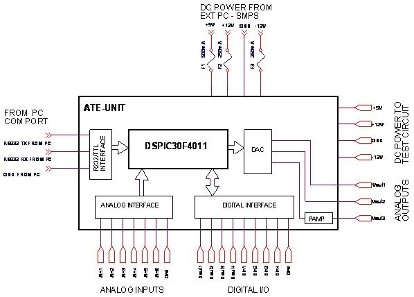
The project, when looked in totality, can be seen as composing of three components, namely LCD, Microcontroller and serial port. The three components have been discussed independently until now and to give a complete picture, it is necessary to link these components.
The linking is not only logical but is also translated into hardware connections. The serial port is connected to the Microcontroller to provide the end user with the functionality of passing a desired string to LCD in run time. An interface between the serial port and the Microcontroller is required for the data transfer. A variable baud rate is generated by the Microcontroller to synchronize the data transfer between the two ends.
The connectivity can be analyzed and understood by the hardware diagram at the end of the chapter. The Microcontroller connects with the LCD with an 8bit interface to for data transfer. Three further pins are required to generate enable, read/write and instruction / data signals for the LCD. These three form a small instruction set that allows different tasks and the functionality provided by the HD44 LCD.
The enable signal is used as a signal to the LCD by the Microcontroller about the availability of data. A high-to-low edge triggers the LCD into reading its data lines. The data meant for the LCD must be present and latched on the data lines before the enable signal switches from high to logic low.
It needs to be understood that data lines for sending instructions and display data are the same, the instruction bits help differentiate among the two for the LCD. The read/write signal specifies to the LCD whether the Microcontroller is intends to read data from its DDRAM/CGRAM or intends to write data to its DDRAM/CGRAM.
In the former case, the data lines contain the data meant for the destination on the LCD memory and in the latter case; the data lines will have the data written onto from the appropriate DDRAM/CGRAM. The instruction/data line specifies whether the data bus contains an instruction or data meant for the LCD.
This signal, along with the instruction bits, help LCD in deciding which control signals to generate to fulfill the request. After sending of every request, whether instruction or data, to the LCD; the Microcontroller must check for the busy flag of the LCD to return to low logic again.
A high logic for the busy flag signals that an internal operation is being carried out and during this time, no external instruction or data is entertained. Only when the busy flag is at a logic low, the Microcontroller should send the next instruction or data.
The busy flag is checked by configuring the LCD into read mode (R/W signal is set to logic high) and then reading the data lines. The MSB of the byte read contains the value of the busy flag. To understand the above concepts, the timing diagram mentioned in Chapter 2 for busy flag testing and data transfer may be used.
Hardware Aspects of Moving Message Display Project, LED BASED MOVING DISPLAY USING 8051, Scrolling Message in LED Display with 8051, 8x8 LED Matrix using 8051, A Microcontroller Based Moving Message Display, Project Help / Display Moving Message, scrolling message display usi 🔗 External reference
Related Circuits
The description pertains to a specific type of preamplifiers that are designed to amplify the low output of Moving coil heads, enabling their drive to an input PHONO [RIAA] of a preamplifier. Moving coil heads present certain challenges that require...
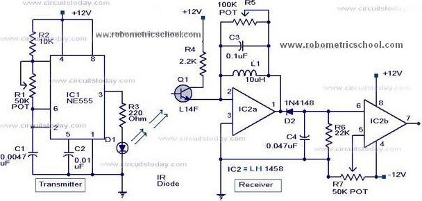
All components used in the Moving Sensor/Detector Schematic Diagram utilize the IC NE555 and the Phototransistor L14F. The primary component in this circuit is the IC NE555, along with an IR LED, the Phototransistor L14F, and the IC LM1458....
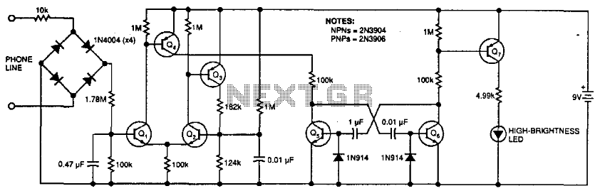
This circuit flashes an LED to indicate that a phone rang during the user's absence. A differential amplifier with hysteresis (Q1, Q2, and Q3) detects high line voltage (ringing), which activates Q4, a multivibrator composed of Q5 and Q6,...
Light emitting diodes are advantageous due to their smaller size, low current consumption and catchy colours they emit. Here is a running message display circuit wherein the letters formed by LED arrangement light up progressively. Once all the letters...
A $35 teaching aid for basic electronics, and an invaluable experimental setup for the electronics hobbyist. It teaches basic analog and digital electronics. The teaching aid is designed to facilitate the understanding of fundamental concepts in both analog and digital...
When the water level is low, the wires in the tank are open-circuited, and the 180K resistor pulls the switch low, resulting in the switch opening and the LEDs turning OFF. As the water begins to fill the tank,...