
Moving Sensor / Detector Schematic Diagram using IC NE555 and Phototransistor L14F

The Moving Sensor/Detector circuit is designed for applications where motion detection is required, such as in security systems or automated lighting. The transmitter circuit, built around the NE555 timer IC, operates in astable mode, generating a continuous square wave signal that drives the IR LED. This LED emits infrared light, which is modulated at a frequency of 5 kHz to improve detection reliability and reduce interference from ambient light sources.
In the receiver section, the Phototransistor L14F is strategically positioned to capture the IR light emitted by the LED. When no motion is detected, the phototransistor remains in a conductive state, resulting in a low output at pin 7 of the LM1458 signal conditioning IC. However, when an object interrupts the infrared beam by moving between the transmitter and receiver, the intensity of the received IR light changes, causing the phototransistor to switch states. This change is detected by the LM1458, which amplifies the signal and produces a high output at pin 7.
The output from the LM1458 can be used to trigger additional circuits, such as a buzzer or an alarm system, providing an audible indication of motion detection. The inclusion of a potentiometer (R5) allows for fine-tuning of the sensor's sensitivity, enabling the user to adjust the circuit's response to varying levels of ambient light or distance from the detected object.
Overall, this Moving Sensor/Detector circuit is a versatile and effective solution for detecting motion in various applications, providing a simple yet efficient means of monitoring movement in a designated area.All components that used in Moving Sensor / Detector Schematic Diagram using IC NE555 and Phototransistor L14F. Main component in this circuit is IC NE555, Led IR, Phototransistor L14F and IC LM1458. Moving sensor / detector schematic diagram divided into two parts, there are transmitter and receiver.
Transmitter part is the par t that will send infra red data using IC NE555 and LED infra red. And in receiver part using photo-transistor L14F that will receive IR signal from LED IR in transmitter. Signal from photo-transistor will allowed through to IC LM1458 as signal conditioner. IC1 (NE 555) is an astable multivibrator which connect with IR LEDs produce infrared rays 5Khz. infrared rays will be received by the photo transistor Q1, if under normal conditions the output pin (7) of IC2 will be low (low).
and if you are moving objects between the transmitter and the receiver on pin 7 of the IC 2 will be conditioned (high). bazzer bell circuit or can be connected to the output of IC 2 is to demonstrate the existence of this disorder.
As note that POT R5 can be used for sensitivity adjustment. Thank you very much for your visiting in Robometricschool blog, We hope you will get more information about Robotic, Mechatronic, and Electronic. And don`t forget to give us your comment about this article. Let keep for building comment. 🔗 External reference
Related Circuits
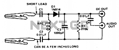
This circuit provides a DC output to a meter and an audio output (if necessary) for checking transmitters or modulated signals. It can also be used as a field strength meter or transmitter monitor. The circuit is designed to facilitate...

Most battery motor speed controllers are under manual control and the operator automatically adjusts speed to match demand. Under these conditions closed loop motor speed control is an unnecessary expense. However, when it is required, a tachogenerator can easily...
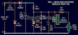
An infrared remote control tester circuit that can be constructed inexpensively. This IR tester is built around an infrared receiver module TSOP1738. The remote control's state can be observed through the sound of a buzzer. The circuit is highly...
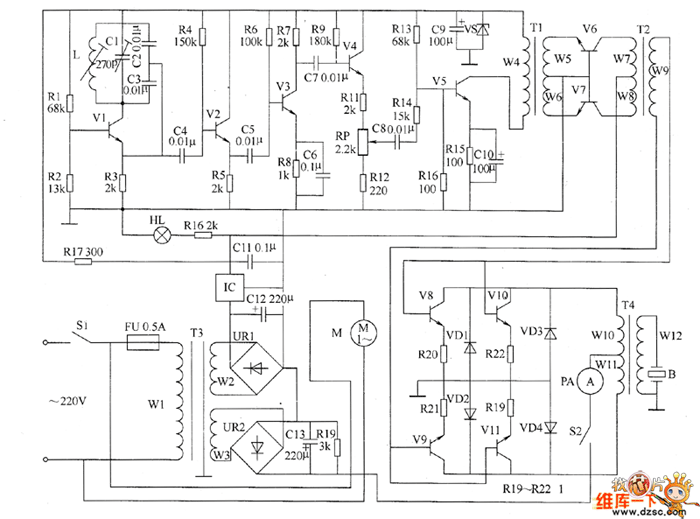
The ultrasonic drilling machine circuit consists of a power supply circuit, an ultrasonic oscillator circuit, a preamplifier, a promoting amplifier circuit, and a power amplifier output circuit, as depicted in the accompanying diagram. The ultrasonic oscillator circuit is made...
If you require a small lamp that flashes for general use, there are numerous options available. Today, three lamp flasher circuits will be presented. The three lamp flasher circuits can be designed using different components and configurations, each offering unique...
This implementation utilizes the L298 integrated circuit to drive motors and inductive loads with a continuous current capacity of up to 4A. The L298 consists of two independent channels, each capable of driving loads of up to 2A. By...