
Harmonic Generator With Single Opamp

This circuit design effectively demonstrates the use of quartz crystals in harmonic generation, leveraging the unique properties of overtone crystals to achieve stable oscillation at desired harmonic frequencies. The configuration of the op-amp as a non-inverting amplifier allows for flexibility in tuning and frequency adjustment, making it suitable for applications where precise frequency control is necessary. The frequency-dependent gain network, composed of R4, R5, and C3, plays a crucial role in ensuring that the circuit can oscillate at the intended harmonics without falling back to the fundamental frequency.
The use of a standard 10 MHz crystal not only simplifies the circuit design but also contributes to the reliability and stability of the output frequencies. The ability to tune the circuit to higher harmonic frequencies provides versatility for various applications in communication and signal processing. The output characteristics, including the ability to drive low-impedance loads, further enhance the practicality of this design in real-world scenarios. Additionally, the consideration of supply voltage limits and output voltage characteristics ensures that the circuit can be safely integrated into larger systems without risk of damage or instability. Overall, this circuit serves as an effective solution for generating stable harmonic frequencies using quartz crystals, with broad applicability in electronic design and engineering.Quartz crystals have the property that their amplitude/phase characteristic repeats itself at frequencies that are an uneven multiple of the fundamental frequency. There are so-called overtone crystals that are cut in such a manner that they possess this property to a greater extent.
However, in principle, any crystal may be used on one or more of its harmonic frequencies. Harmonic generators based on transistors may operate satisfactorily on the 3rd harmonic, but if the 5th or 7th harmonic are wanted, the circuit becomes less reliable and requires frequent adjustment. This circuit is based on a single, fast opamp and oscillates readily at the 3rd, 5th or 7th harmonic.
The opamp is set up as a non-inverting amplifier with the quartz crystal connected between its output and the non-inverting input. The circuit amplification, which in principle must be unity to ensure oscillation, is determined by the network formed by R4, R5 and trimmer capacitor C3.
This network is frequency-dependent such that the amplification increases as the frequency rises. The network gain is adjustable with C3. The setting of the capacitor must be such that the gain is too small for oscillation at the fundamental frequency, but sufficient for, say, the 5th or 7th harmonic. The author uses a standard computer crystal of 10 MHz. Depending on the setting of C3, the circuit provides a stable output at frequencies between 50 and 70 MHz.
It should be noted that these frequencies are multiples of the series fundamental frequency of the crystal. Tuning is carried out simply with a frequency counter. The output frequency is varied with C3. When the capacitor is roughly at the correct setting, the frequency locks` as it were at the harmonic.
The area where locking occurs is not well-defined, however, so that the setting of C3 is not critical. When tuning is completed, the output frequency is crystal-stable. In principle, the circuit may be used for frequencies of up to 100 MHz, when the values of R4 and R5 may need to be reduced.
When a crystal with a higher fundamental frequency, say, 15 MHz, is used, the circuit may be tuned to the 3rd harmonic, that is, 45 MHz. The circuit should be tested with a supply voltage of 5 9 V (the maximum supply voltage for the IC is 12 V).
The peak to peak output voltage has a value of about that of the supply voltage less a few volts. The output can provide a current sufficient to drive relatively low-impedance loads. 🔗 External reference
Related Circuits
This circuit generates sine waves ranging from 1 kHz to 25 kHz with a total harmonic distortion (THD) of better than -80 dB. It comprises a 4th-order low-pass filter and a TTL counter. The circuit utilizes a sine wave oscillator...
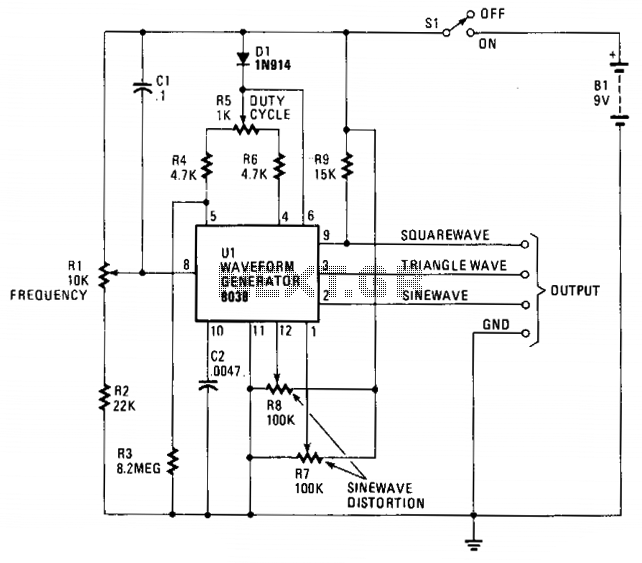
The circuit is designed around the Intersil 8038CC. The frequency range is approximately 20 Hz to 20 kHz, providing a tuning range of 1000:1 with a single control. The output frequency is determined by the value of capacitor C2...
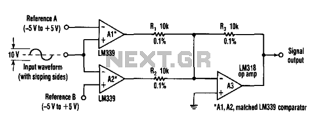
This circuit can extract harmonics from various waveforms. With a sloped input waveform, the comparator produces a pulse width that is proportional to a reference plus input amplitude. As the pulse width changes, the harmonics spectrum changes. Combining the...
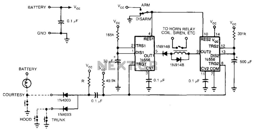
With a single integrated circuit (IC), it is possible to construct a straightforward and dependable auto burglar alarm or a similar alarm system. Refer to (a) for the timing information related to the alarm circuit in (b). When leaving...
The foundation of an audio mixer is an inverting summing circuit. In practical audio mixers, a single-supply voltage is rarely utilized. To enhance dynamic range, ... The inverting summing circuit serves as a fundamental building block in audio mixing applications,...
A dual-axis solar tracker system circuit is designed to automatically adjust the solar panel's orientation to remain perpendicular to the incident sunlight throughout the day. Implementing this system involves complex mechanisms and circuitry, which may not be easy for...