
easiest single axis solar tracker

In contrast, the simpler single-axis system described here can be constructed quickly and easily, though it requires periodic adjustments every month. Initially, the system may achieve 100% efficiency, but performance will decline over time without maintenance to adapt to the sun's changing positions throughout the year. The concept involves recording the average duration of sunlight exposure and adjusting the motor speed to rotate the panel from sunrise to sunset, maintaining an alignment with the sun's trajectory. The motor is expected to rotate the panel through an angle of approximately 50 to 60 degrees during this period. A pulse-width modulation (PWM) circuit is utilized to control the motor speed, which can be a stepper motor or a standard brushless motor.
To optimize the system's efficiency, motor speed adjustments must be recorded and fine-tuned over several days. This data will facilitate future seasonal adjustments without ongoing monitoring. A diagram illustrates a basic motor and gear mechanism for the proposed system, with a blue plate representing the solar panel attached to the central rod of a larger gear. The motor control circuit is built around an inexpensive 555 integrated circuit and other essential semiconductor components. A potentiometer (P1) should be mounted externally to allow for easy speed adjustments throughout the year, ensuring the panel's rotation is synchronized with the sun's movements. Careful calibration of P1 is necessary to maintain a consistent motor speed. The gear arrangement must ensure that the interaction between the smaller and larger gears results in a steady angular movement of the panel, keeping it perpendicular to the sun's rays throughout the day. Each time the settings are refreshed, the P1 adjustment should be documented for future reference and repeated in subsequent years.A dual axis solar tracker system circuit which is intended forautomaticallyadjusting the solarpanelface such that it stays perpendicular to the incident sun rays at all instants. throughout the day. However for this to happen whole set up involves many complex mechanisms and circuitry which may not be easy for all to assemble and implement.
If youare readyto sacrifice and ignorea fewof the luxuries provided by the above dual axis tracker, then probably you would like to go with the concept explained in the present article. The previously discussed dual axis solar tracker post included some sensors in the form of LDRs for monitoring the suns "position in the sky" and accordingly providing thecommandsto the control circuit and the motor so that necessary adjustments are quickly made to the panel for maintaining the required accuracy of the panel with the sun rays.
The system requires some criticalsettingandadjustments, however once these are completed you just watch the whole thing do the rest for the rest of your life providing 100% efficiency with the involved electrification of your house. Here, since we do not incorporate any sensor and the system is a single axis type can eb built very easily and quickly, but you will have to do some tedious settings in thebeginningand keep repeating it once every month or so.
The efficiency of this system may well be 100% in theinitialstages but will go ondeterioratingas weeks progress until you refresh and restore the original settings. This must be done in response to th changing sunrise/sunset positions of the sun through out the year.
The concept is simple, we just note down the average time for which the sun remains active or live over the sky. Then we adjust the speed of the motor such that it rotates the panel from sun rise to sun set more or less facing the sun throughout its rotation.
The speed of the motor thus gets adjusted which moves the panel through a angle of may be around 50 to 60 degrees throughout thestipulatedperiod, imitating to be following the suns track. The circuit used for adjusting the motor speed isobviouslya PWM circuit and the motor used may be a stepper type of motor or even an ordinarybrush-lesstype will also do.
The adjustment of the speeds in response to the daylight period must be optimized for many days for making the system as efficient as possible. The date and the relevant of the setting of the speeds must be noted down for records so that the same setting can be applied withoutmonitoringfor thefutureseasons.
The following figure shows a simple motor and gear mechanism which may employed for the proposed system. The blue colored plate is the solar panel, which is fixed with the larger gears central rod. The following circuit shows the motor control circuit which involves a simple circuit made from a cheap 555 IC and some other important semiconductor parts.
Pot P1 should be mounted outside the enclosure in which the circuit may be covered. P1 is the main component which may be used for adjusting the motor speeds during different seasons of the year such that the panel rotation remains more or lesssynchronizedwith the sun "movements". In fact P1 may have to be adjusted very carefully such that the motor operates at some fixed speed. The gear mechanism should be arranged such that the smaller gear and the larger gear diameters produce a constant angular movement to the panel in order to keep the panel face more or less perpendicular to the sun throughout the day.
The setting of P1 should be noted down each time the settings are refreshed corresponding to thedifferentmonths of the year. This data may then be repeated for the future years. 🔗 External reference
Related Circuits
The approximate center of the base was marked, and a hole was drilled large enough to accommodate a setscrew for the servo armature. The armature was then secured to the underside of the base using hot glue, ensuring that...
The simplest current-to-voltage (I to V) converter is a basic resistor. However, the disadvantage of this simple configuration is that it presents a nonzero impedance to the input current source. The I to V converter is an essential circuit in...
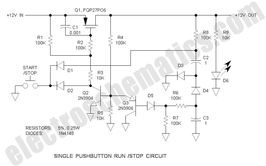
There are solutions to this problem—mechanical (push On/push Off switch), electromagnetic (latching relay), and electronic (CMOS logic), but few (if any) go... In addressing the problem of circuit control, several methods are available, including mechanical, electromagnetic, and electronic solutions. Mechanical...
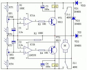
The following circuit illustrates an LM358 integrated circuit solar controller circuit diagram. Features include its application in mobile communications base stations and conversion capabilities. The LM358 is a dual operational amplifier that is commonly used in various applications, including solar...
Children enjoy the siren sounds of police or fire brigade vehicles. This circuit is capable of generating a dual tone similar to the siren sounds of police or fire brigade cars. This circuit typically... This circuit is designed to replicate...
The circuit involves powering an LED using a 3V CR2032 battery, with the intention of extending battery life by making the LED blink rather than remain continuously on. A 555 timer is considered, utilizing large value resistors in the...