
Harmonic Generator

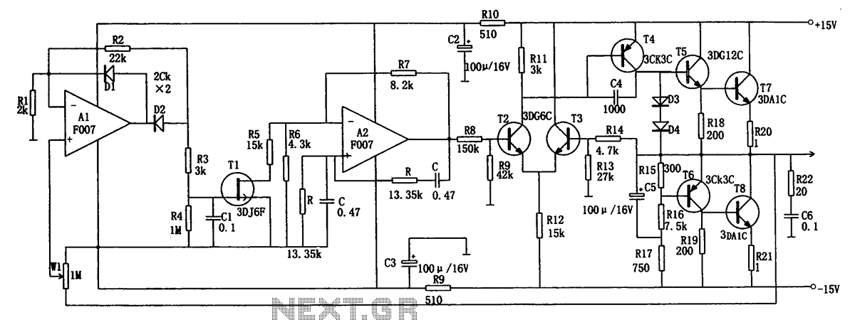
The described circuit is designed for harmonic extraction from diverse waveform sources, effectively allowing for the manipulation and analysis of harmonic content. The operation begins with a sloped input waveform applied to a comparator, which generates a pulse width that corresponds to the sum of a reference voltage and the input amplitude. This pulse width modulation facilitates the alteration of the harmonic spectrum, enabling the circuit to produce varying harmonic frequencies based on the input characteristics.
The circuit includes two comparators, which output signals that can be combined for further processing. The combination of these outputs is crucial, as it allows for the cancellation of certain harmonics, influenced by the duty cycle of the output signals. By carefully adjusting the reference voltages applied to the comparators, it is possible to tailor the circuit to generate virtually any harmonic frequency desired, enhancing its versatility in harmonic analysis and synthesis applications.
For optimal performance, it is essential that the operational amplifiers Al and A2 are closely matched to ensure consistent behavior across the circuit. Resistors Rl and R2 should be selected with a tolerance of 0.1% to minimize variations that could adversely affect the circuit's performance. Additionally, operational amplifier A3 must exhibit high common-mode rejection and a rapid slew rate, allowing it to accurately respond to fast-changing signals without distortion.
This circuit can find applications in various fields such as audio signal processing, waveform generation, and electronic musical instruments, where precise harmonic manipulation is required. This circuit can extract harmonics from various waveforms. With a sloped input waveform, the comparator produces a pulse width that is proportional to a reference plus input amplitude. As the pulse width changes, the harmonics spectrum changes. Combining the two comparator outputs eliminates some harmonics, depending on the duty cycle. Adjusting the references can create virtually any harmonic. Al and A2 should be matched, Rl and R2 should be equal to 0.1%, and A3 should have good common-mode rejection and high slew rate.
Related Circuits
The low-frequency signal generating circuit demonstrates excellent performance characterized by stable operation, high output power, and minimal waveform distortion. It serves as an ideal source for low-frequency measurement signals. The circuit includes an operational amplifier (A) with a feedback...
The simplest way to harness free available energy is by utilizing solar cells. A single efficient solar cell, when paired with a well-configured HHO generator, can produce a significant amount of gas suitable for various applications, all without incurring...
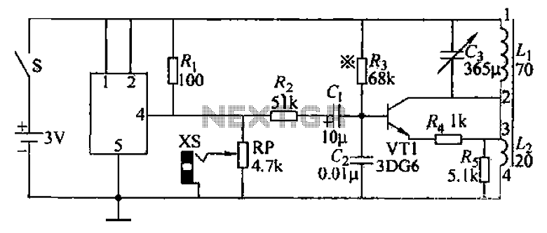
An audio frequency signal generator can output audio signals, 465 kHz spectral amplitude signals, and 52.5 Hz to 16 kHz high-frequency amplitude-modulated signals. The high-frequency oscillator's vibration frequency is determined by the components G and L. A variety of...
Marx Generators are commonly utilized in pulsed power and high voltage applications to produce a high peak voltage pulse. The fundamental principle behind these generators involves charging several capacitors in parallel, followed by closing switches to connect them in...
This circuit diagram illustrates a triangular wave generating circuit utilizing a pair of operational amplifiers (Op-Amps). The LM741 Op-Amp is recommended for this application. The first Op-Amp, located on the left, functions as a comparator, while the second Op-Amp...
This is a simple sawtooth generator circuit. The advantages of this circuit include low cost and the ability to produce an auxiliary square wave at the same frequency. This circuit can be utilized to sweep the frequency of another...