
HARTLEY OSCILLATOR
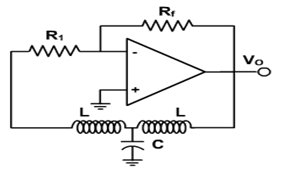
The Hartley oscillator operates on the principles of resonance and feedback, utilizing an inductor-capacitor (LC) tank circuit to generate oscillations. In this configuration, the two inductors (L1 and L2) are connected in series, with a capacitor (C) connected in parallel to the tapped coil. The feedback mechanism is crucial for sustaining oscillations, as it allows a portion of the output voltage to be fed back into the circuit to maintain the oscillation process.
The tank circuit's resonant frequency is calculated using the formula:
\[ f = \frac{1}{2\pi\sqrt{L_{\text{total}}C}} \]
where \( L_{\text{total}} \) is the equivalent inductance of the series-connected coils. For a Hartley oscillator, this can be expressed as:
\[ L_{\text{total}} = L1 + L2 \]
This equation showcases how the inductance values directly influence the oscillation frequency. The feedback fraction is critical, as it determines whether the circuit will sustain oscillations. The condition for oscillation is that the loop gain must be equal to or greater than one, which is achieved when the feedback voltage is appropriately scaled.
In practical applications, the Hartley oscillator is favored for its simplicity and effectiveness in generating sine wave signals. It is commonly used in RF applications, signal generators, and other electronic devices requiring stable oscillation frequencies. The design can be adjusted by varying the values of L1, L2, and C to achieve the desired frequency response, making it a versatile choice in electronic circuit design.The Hartley oscillator is an LC electronic oscillator that derives its feedback from a tapped coil in parallel with a capacitor (the tank circuit). Although there is no requirement for there to be mutual coupling between the two coil segments, the circuit is usually implemented as such.
A Hartley oscillator is essentially any configuration that us es a pair of series-connected coils and a single capacitor. In the oscillator, the feedback voltage is developed by the inductive voltage divider, L1 & L2. Since the output voltage appears across L1 and the feedback voltage across L2, the feedback fraction is As usual, the loading effect of the base is ignored. For oscillations to start, the voltage gain must be greater than 1/ ². The frequency of oscillation is given by 🔗 External reference
Related Circuits
The figure illustrates the FM modulation circuit of a crystal oscillator. FM modulation can be achieved through direct and indirect methods. The direct FM method involves directly altering the frequency of the oscillating circuit. While this approach is straightforward,...
This chapter discusses the operation and circuitry of transistor oscillators, which can be categorized into two types: feedback (similar to vacuum tube oscillators) and negative-resistance (current multiplying). Transistor oscillators can generate sine waves using various operational modes, including some...
The beat frequency oscillator (BFO) is essential for receiving continuous wave (CW) signals. Since CW signals lack an audio modulation component, it is necessary to introduce one. The functions of the RF amplifier, mixer, local oscillator, and IF amplifier...
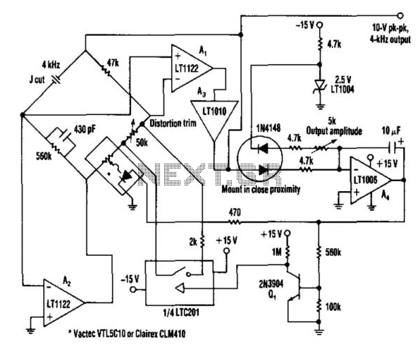
This oscillator utilizes a bridge circuit with an optoisolator functioning as a gain-control device. The resultant distortion can be maintained at 9 ppm (0.0009%) with appropriate adjustments. The oscillator circuit described operates using a bridge configuration, which is a common...
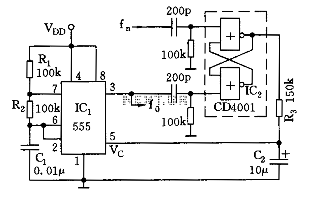
The circuit illustrated consists of a 555 timer along with resistors R1 and R2, and capacitor C1, forming a composition-controlled multivibrator. The oscillation frequency is influenced not only by the RC time constant but also by the adjustment of...
The circuit was designed to operate a frequency modulation voice transmitter over the FM band within the VHF frequency range. The transmitter is an electronic device. The frequency modulation (FM) voice transmitter circuit operates within the VHF (Very High Frequency)...