
Fundamentals of Transistor Oscillators
Transistor oscillators are essential in various applications, including signal generation and clock pulses in digital circuits. The feedback mechanism in these oscillators is crucial for maintaining oscillation. The resonant tank circuit typically consists of an inductor and capacitor, which determines the frequency of oscillation. The choice of components and their values directly impacts the stability and frequency of the generated signal.
In the feedback oscillator configuration, the feedback resistor plays a vital role in setting the gain of the circuit. A choke can be used in place of a resistor to improve performance by allowing higher frequency signals to pass while blocking DC. The design of the tank circuit must consider the quality factor (Q) to ensure minimal energy loss, which is critical for achieving sustained oscillations.
The analysis of relaxation and frequency division is particularly important in applications such as pulse-width modulation and frequency synthesis. By adjusting the feedback and component values, it is possible to create oscillators that operate over a wide range of frequencies and output waveforms.
In conclusion, understanding the operational principles and configurations of transistor oscillators allows engineers to design robust and efficient circuits tailored to specific applications. The versatility of these oscillators makes them fundamental in both analog and digital electronics, providing essential functionalities in various electronic systems.This chapter deals with the operation and circuitry of transistor oscillators. In general, these fall into two categories: the feedback (or vacuum tube equivalent) types, and the negative-resistance (or current multiplying) type. Transistor oscillators are capable of sine-wave generation by every mode of operation now feasible in vacuum-tube circu
its, plus some additional novel modes. This chapter covers the capabilities of the transistor as an oscillator in basic rather than specific designs. A number of numerical examples and specific values are included to illustrate the fundamental concepts involved.
An analysis of relaxation, frequency multiplication, frequency division, and triggering in the transistor is also included. In the earlier chapters, it was shown that transistor properties, in every important respect, are equivalent to those of the vacuum tube.
It is reasonable then to assume that any vacuum-tube oscillator configuration has an equivalent transistor circuit. For example, consider the vacuum-tube oscillator, illustrated in Fig. 6-1 (A), which represents one form of Hartley oscillator. Positive feedback is accomplished by arranging the resonant tank E to be common to both the input grid and output plate circuits.
The equivalent transistor circuit using a grounded emitter connection is illustrated in Fig. 6-1 (B). Again, positive feedback is provided by placing the resonant tank so that it is common to both the input base and output collector circuits. If ground is removed from the emitter lead, and placed at the bottom of the tank circuit, the electrical operation of the oscillator is unchanged.
Notice that when this circuit is rearranged as illustrated in Fig. 6-1 (C), it is now in the grounded-base connection. While the grid bias of the vacuum-tube oscillator in Fig. 6-1 (A) is regulated by the grid leak resistor RG, the equivalent transistor base in Fig. 6-1 (C) is self-biased through resistor RB. In all three circuits, the battery supply is decoupled by an R-F choke. The major difference between the operation of the vacuum-tube Hartley oscillator and that employing a transistor lies in the loading effect of the emitter resistance on the tank coil. This resistance is reflected into the tank circuit and acts as an equivalent shunting resistance. The tank is also shunted by the collector resistance, and the equivalent shunt resistance of the resonant circuit becomes Oscilation starts when the equivalent shunt resistance of the tank is counterbalanced by the reflected negative-resistance of the emitter.
The optimum tap point of the coil (as determined both mathematically and experimentally) is, where T is the ratio of the feedback turns included in the emitter circuit to the total number of tank coil turns, and a is the emitter-to-collector current gain. Notice that when a approaches unity, the transistor oscillates at highest efficiency with a center-tapped tank coil.
Under this condition the minimum allowable parallel resistance of the tank circuit is resistance, fo is the resonant frequency, and L is the inductance of the tank coil. The operating resonant frequency is always lower than the isolated resonant tank frequency, because of the change in effective value of inductance caused by the coil tap.
The disadvantages of tapping the coil can be avoided by using a direct feedback path from the resonant circuit to the input terminal. Figures 6-2 (A) and 6-2 (B) illustrate two such possible arrangements. In both examples, the feedback resistor RF (a choke may be used) and the effective impedance of the resonant circuit form an a-c voltage divider.
The value of RF can be adjusted to obtain the required amount of feedback for sustained oscillation. The transistor equivalent of the Clapp oscillator is illustrated in Fig. 6-3 (A). The operating frequency is set by the series resonant circuit in the collector circuit. Feedback is taken from the voltage d 🔗 External reference
Related Circuits
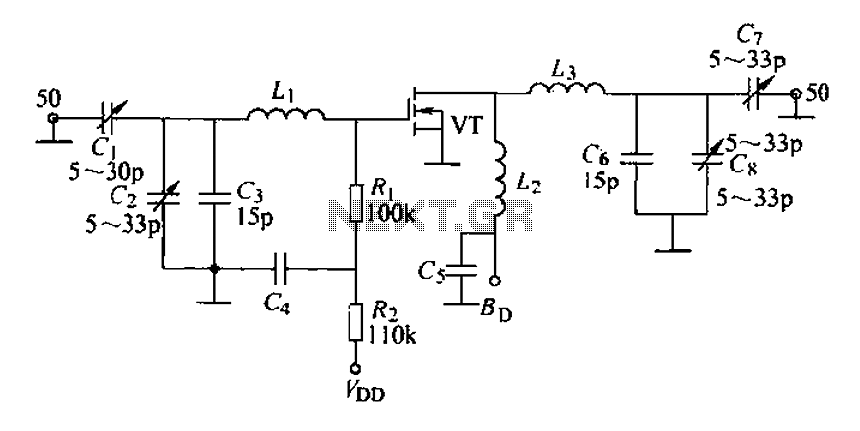
A 175 MHz high-frequency amplifier circuit utilizing a field-effect transistor (FET) is presented. The field-effect transistor used is the 3D04H, along with its associated components and parameters. The 175 MHz high-frequency amplifier circuit is designed to amplify signals in the...
The circuits discussed here are simple LED flashers that typically illuminate one or two LEDs, contrasting with more complex light chaser circuits that can flash four or more. While the most basic option is a flashing LED, it lacks...
The schematic illustrates the division of a crystal oscillator signal by the crystal frequency to achieve a precise 1-second time base with an accuracy of 0.01%. Two cascaded 12-stage counters (CD4040) create a 24-stage binary counter, with specific bits...
If you require a small lamp that flashes for general use, there are numerous options available. Today, three lamp flasher circuits will be presented. The three lamp flasher circuits can be designed using different components and configurations, each offering unique...
The design objective was to produce an hFE tester with switched collector currents for the DUT (Device Under Test) covering a range suitable for the selection and matching of output transistors for amplifiers such as the JLH Class-A, ESP...
Most surviving TR-1 radios no longer function. Many collectors prefer to maintain them in their original condition to preserve authenticity. However, there may come a time when one wishes to hear the radio play. Before proceeding with any modifications,...
Warning: include(partials/cookie-banner.php): Failed to open stream: Permission denied in /var/www/html/nextgr/view-circuit.php on line 713
Warning: include(): Failed opening 'partials/cookie-banner.php' for inclusion (include_path='.:/usr/share/php') in /var/www/html/nextgr/view-circuit.php on line 713