
Hartley Oscillator Tutorial and Oscillator Design

The Hartley oscillator is a type of electronic oscillator that generates sine waves using an inductor-capacitor (LC) tank circuit. It is characterized by its use of two inductors and a single capacitor to determine the oscillation frequency. The basic configuration includes a transistor that acts as an amplifier, and the feedback necessary for oscillation is provided by the LC tank circuit.
In a typical Hartley oscillator circuit, two inductors (L1 and L2) are connected in series with a capacitor (C). The total inductance is given by the formula L_total = L1 + L2. The frequency of oscillation can be calculated using the formula:
f = 1 / (2π√(L_total * C))
where f is the frequency in hertz, L_total is the total inductance in henries, and C is the capacitance in farads. The choice of inductors and capacitors directly affects the output frequency and stability of the oscillator.
The transistor, which can be either bipolar junction or field-effect, amplifies the signal generated by the tank circuit. The feedback loop is critical for sustaining oscillations, and it is achieved by connecting a portion of the output back to the input through the LC circuit. The phase shift around the loop must be 360 degrees for sustained oscillation, which is typically achieved by ensuring that the total phase shift through the transistor and the tank circuit meets this requirement.
Hartley oscillators are commonly used in radio frequency applications due to their ability to produce stable sine wave signals. They are also valued for their simplicity and ease of tuning, which makes them suitable for various applications, including signal generation and modulation. When designing a Hartley oscillator, careful consideration must be given to component selection, layout, and power supply to ensure optimal performance and minimize distortion in the output waveform.Hartley Oscillator Tutorial and the theory behind the design of the Hartley Oscillator which uses a LC Oscillator tank circuit to generate sine waves.. 🔗 External reference
Related Circuits
Circuit CREATOR Electronics CAE System provides the most complete and high performance solution for electronics design using personal computers. More: Includes PCB DESIGN -layout editor and Schematic Capture software tool, full Schematic Design and Capture, Circuit Simulation, full interactive...
The Colpitts oscillator circuit schematic is closely related to the shunt-fed Hartley oscillator, with the primary distinction being in the tank circuit design. In the Colpitts oscillator, two capacitors are utilized in place of divided coils. The basic feedback...
An astable multivibrator needs to be designed, and the maximum and minimum frequencies generated at the output must be calculated. An astable multivibrator is a type of oscillator circuit that continuously switches between its high and low states without requiring...
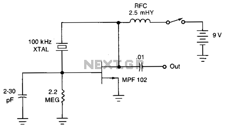
The JFET Pierce oscillator is stable and straightforward. It can serve as the clock for a microprocessor, a digital timepiece, or a calculator. With a probe connected to the output, it can function as a precise injection oscillator for...
Prolonged reading or writing, maintaining a close distance between the eyes and the book, and insufficient lighting are primary contributors to decreased vision. This example describes a visual fatigue eliminator designed to alleviate eye fatigue and prevent myopia. The...

Almost any transistor will work. R1 and C1 will vary the tone. The circuit utilizes a transistor as the primary active component, which can be substituted with various types of transistors, including bipolar junction transistors (BJTs) or field-effect transistors (FETs)....