
Design of astable multivibrator

An astable multivibrator is a type of oscillator circuit that continuously switches between its high and low states without requiring any external triggering. This circuit is commonly built using bipolar junction transistors (BJTs) or operational amplifiers (op-amps), but it can also be constructed using integrated circuits such as the 555 timer.
The basic configuration consists of two resistors (R1 and R2) and a capacitor (C) connected to the timing circuit. The output frequency (f) of the astable multivibrator can be calculated using the formula:
f = 1.44 / ((R1 + 2 * R2) * C)
In this equation, R1 and R2 are the resistances in ohms, and C is the capacitance in farads. The maximum frequency occurs when R1 and R2 are minimized, while the minimum frequency occurs when these resistances are maximized.
To derive the maximum frequency, the values of R1 and R2 should be as low as possible. Conversely, for the minimum frequency, the resistances should be maximized. The choice of capacitor value (C) also plays a significant role, as it directly influences the timing intervals.
In practical applications, it is essential to consider the tolerances of the components used, as variations can affect the output frequency. Additionally, the supply voltage and power ratings of the components must be suitable for the intended application to ensure reliable operation.
In summary, designing an astable multivibrator requires careful selection of resistor and capacitor values to achieve the desired output frequencies. Calculating the maximum and minimum frequencies is crucial for ensuring that the circuit meets its intended performance specifications.Hello sir, I need to design an astable multivibrator and supposed to calculate the maximum and minimum frequency generated at the output. Can you.. 🔗 External reference
Related Circuits
Feedback - This is where part of the output signal is fedback to the input BUT 180° out-of-phase (i.e. partially cancels the input). If it were in-phase feedback then we would have an oscillator - which in this case...
A standard 12-volt automotive electrical system can be viewed as a robust yet unreliable source of low-voltage DC current. Any mobile PC installation should encompass several features, as automotive systems must adhere to strict electrical standards. The starter motor...
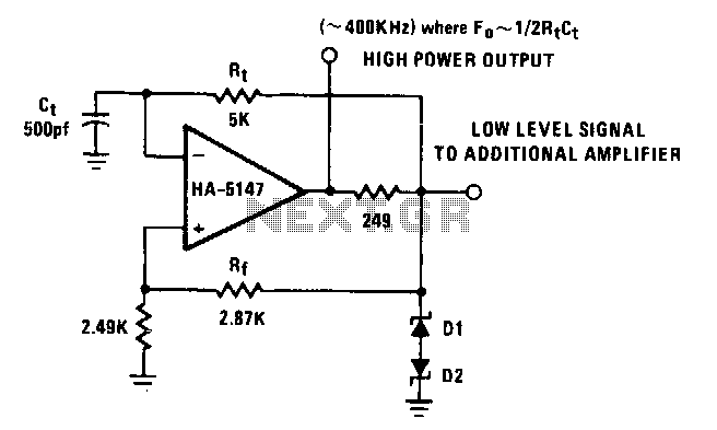
The power bandwidth of the HA-5147 extends the circuit's frequency range to approximately 500 kHz. Resistor R can be made adjustable to vary the frequency if desired. Any timing errors due to Vas or hu have been minimized by...
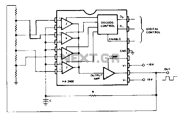
This is the simplest programmable oscillator circuit, requiring only one stable timing capacitor. The output square wave has a peak-to-peak voltage of approximately 25 V, with rise and fall times of about 0.5 µs. Additionally, if a programmable attenuator...
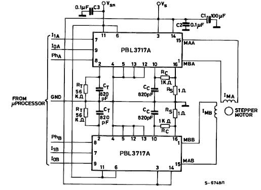
The PBL3717A stepper motor driver is a monolithic integrated circuit that controls and drives one phase of a bipolar stepper motor utilizing chopper control for phase current regulation. Current levels can be selected in three increments using two logic...
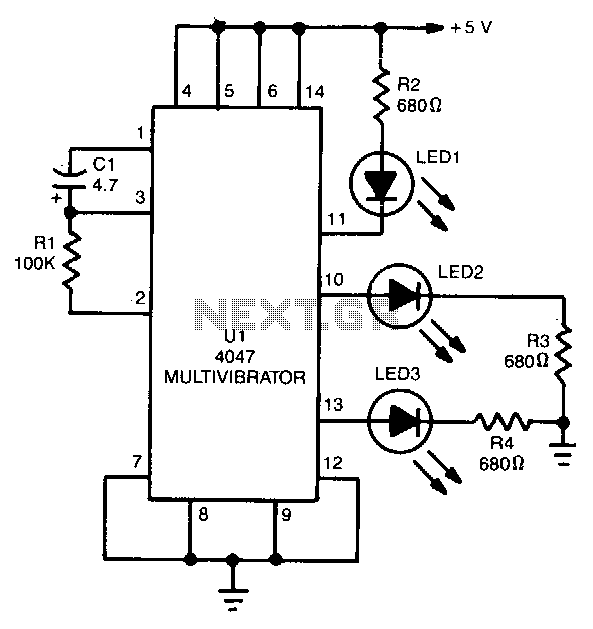
The 4047 is configured as a free-running astable multivibrator (oscillator) circuit. This configuration offers three different outputs. The output pulses at the Q and Q output (pins 10 and 11, respectively) are the same as in the previous two...