
Interpretation of visual fatigue eliminator Circuit Design

The visual fatigue eliminator circuit is designed to address common causes of eye strain by creating an engaging visual stimulus that encourages the user to maintain a proper distance from screens or reading materials. The pulse generator circuit, utilizing the NE555 timer IC, operates in astable mode to produce a square wave output which generates a series of pulses. These pulses are fed into the CD4017 decade counter, which sequentially activates the LEDs based on the input pulses it receives. The arrangement of the LEDs is critical; their symmetrical positioning ensures that the light emitted is evenly distributed, promoting even eye movement and reducing the likelihood of fatigue.
The selection of components is also crucial for the circuit's performance. The use of 1/4W resistors provides adequate current limiting for the LEDs, ensuring they operate within safe parameters while still providing sufficient brightness. The choice of capacitors, whether monolithic or polyester, contributes to the stability and reliability of the pulse generator, while the 1N4148 diodes are well-suited for switching applications, ensuring rapid response times in the pulse divider circuit.
Overall, this circuit serves as an effective tool for combating visual fatigue, particularly in environments where prolonged focus is necessary, such as reading or using digital devices. By incorporating this visual fatigue eliminator into daily routines, users can help mitigate the risks of developing myopia and other vision-related issues.A long time reading, writing, the distance between the eyes and the book too close, the light is too dark, etc. are the main cause of decreased vision. This example describes t he visual fatigue eliminator, can help to eliminate eye fatigue, prevention of myopia. Circuit works The elimination of visual fatigue from the pulse generator circuit, the count divider and LED display circuit, as shown in FIG. Circuit, the pulse generator circuit by the time-base integrated circuit IC 1, the resistors R1, R2, diode VD1 and capacitor Cl, C2 composition; counting by the divider circuit decimal counting/pulse distributor integrated circuit IC2 and diode VD2 - VD11 composition; LED display circuit consists of resistors R3 - R6 and a light-emitting diode VLl V L4 components.
After the pulse generator power work, ICl 3 feet oscillation signal output from the pulse count as IC2. IC2 after power-on reset, in the role of the input pulse, its YO Y9 end a cycle of the output high, drive VL1 a VM cycle according to certain rules kept light.
When the end of IC2 YO, Y4 and Y7 end-side output high, VLI is lit; the Y1 end, when Y6-side output high, V L2 is lit; at the end of Y2, Y5 and Y9-ended output high-end power usually, V L3 is lit. At the end of Y3 and Y8-side output high, V L4 is lit. VLI order a light emitting diode emitting VL4 is VLl-VL2-L3-VL4-VLl-VL3-VL2-VL1-VL4-VL3-VLl-VL2 continuous loop.
The four light emitting diode (VLI V a fight) are mounted on a plane, down, left and right positions symmetrical with each other (up, down or left and right distance corresponding to the two light-emitting diodes is about 30mm). When the eye fatigue, eye with light-emitting diode light kept turning off (when in use, the distance between eyes and the light emitting diode is 25 - 30cm), to achieve the elimination of eye fatigue, the purpose of prevention of myopia.
Component selection Rl a R6 use 1/4W carbon film resistors or metal film resistors. C1 and C2 use monolithic capacitors or polyester capacitors. VD1 VD11 are made of a 1 N4148 silicon switching diodes. VU a VL4 are made µ5mm or µmm green high-brightness light-emitting diodes. IC 1 NE555 type used when the base integrated circuit; IC2 use CD4017 type decimal counting/pulse divider circuit.
Related Circuits
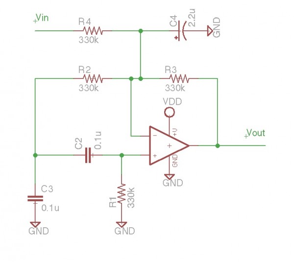
It is essentially an all-pass filter with two additional components: a capacitor and a resistor, which produces percussion sounds. A schematic of the unmodified all-pass filter circuit, a waveform captured via Audacity, and a short audio sample featuring a...
This receiver, designed around the popular ZN414 integrated circuit, operates within the AM band frequency range of 550 to 1600 KHz. For Longwave reception, it is necessary to replace the coil, which can be sourced from an old medium...
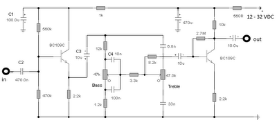
The first BC109C transistor functions as a buffer, delivering a high input impedance of approximately 250k and exhibiting a voltage gain marginally below unity. Given that the Baxendall tone control circuit operates passively, it attenuates all audio frequencies. The...
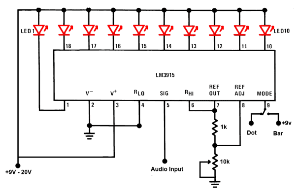
This is a simple audio sound level LED display circuit diagram. The circuit is entirely based on a single integrated circuit, the LM3915 from National Semiconductor. The LM3915 is a monolithic integrated circuit that displays the audio sound level...
This is a portable, high-power incandescent electric lamp flasher. It functions as a dual flasher (alternating blinker) capable of managing two independent 230V AC loads (bulbs L1 and L2). The circuit is entirely transistorized and operates on battery power....

The precision Phase Locked Loop (PLL) in this circuit operates similarly to a basic PLL, but with several enhancements. The flip-flops in the detector are equipped with a gate G1 to clear them, allowing for a faster response. The...