
Head light high beam the dimmer relay or the fuses for that circuit
The headlight circuit operates through a series of interconnected components, including the headlight switch, relay, and fuse box. The headlight switch is responsible for controlling the flow of current to the headlights. When the switch is activated, it completes the circuit by connecting the blue wire to ground, which in turn energizes the lighting relay. The relay acts as a switch that allows a higher current to flow from the battery to the headlights without overloading the switch.
In the scenario described, troubleshooting involves checking continuity and power at various points in the circuit. The relay's smaller terminals (A and D) should be tested for power when the relay is engaged, while the larger terminals connect to the headlight circuit. The continuity checks between terminals C and the blue wire, as well as between C and B, confirm that the relay is functioning correctly and that the switch is providing the necessary signals.
The presence of power at the dimmer relay terminal when a wire is connected from the battery to the headlight fuse indicates that the circuit is incomplete elsewhere, likely due to an open circuit between the headlamp switch and the under-hood fuse box. This suggests that further investigation is needed in the wiring that connects these components. It is also critical to ensure that there is continuity from terminal 5 to ground, as this will confirm that the headlight switch is properly grounded and capable of completing the circuit.
To summarize, a thorough examination of the wiring diagram, continuity testing, and power checks at each component in the headlight circuit will aid in diagnosing the issue effectively. Properly identifying the fault will facilitate the necessary repairs to restore functionality to the headlight system.If you ground the blue wire at the headlamp switch and the lights come on the switch is bad. I know you have already checked continuity of the switch though. If I recall the relay has 2 small terminals and 2 larger ones. The one smaller one should that has no power with the relay out should have continuity to the blue wire at the light switch. what i believe is that i have an open circuit between headlamp swicht and underhood fusebox, can i please get the wiring diagram for headlight circuit, if youcan hey, steve this problem is killing my brains, i need your help to try and figure this out. did some more testing and this is what i found, a-d terminal on lightning relay both have power, continuity good between terminal C and blue wire on headlampswicht.
C-B terminal both on Light relay have continuity to blue wire lightswicht. also continuity good on C-B terminal to black wire on lightswicht. (2)all dimmer relay wires have good continuity to lightswicht. (3)how come when i run wire from + battery to headlight fuse headlight comes on and also i get power on dimmer relay terminal. The blue wire goes through the headlight switch to ground to make the lighting relay operate. There has to be continuity between terminal 5 and 18 in the light switch with the connector unplugged.
And we need to check continuity from 5 to ground. Ask-a-doc Web sites: If you`ve got a quick question, you can try to get an answer from sites that say they have various specialists on hand to give quick answers. Justanswer. com. Traffic on JustAnswer rose 14 percent. and had nearly 400, 000 page views in 30 days. inquiries related to stress, high blood pressure, drinking and heart pain jumped 33 percent. 🔗 External reference
Related Circuits

This project addresses a common need by providing a simple circuit designed to dim LED lights or control the speed of 12V DC motors. The circuit employs Pulse Width Modulation (PWM) to regulate the effective or average current flowing...
The inductor is made by winding 8 turns of #24 insulated solid copper wire on a 5 mm screwdriver. I used a conductor from a piece of category 5 quad twisted pair, left over from wiring the house with...
This is the simplest VU meter that can be constructed. It is based on a single integrated circuit. A volume unit (VU) meter, or standard volume indicator, is a device used to display the level of any voltage signal...
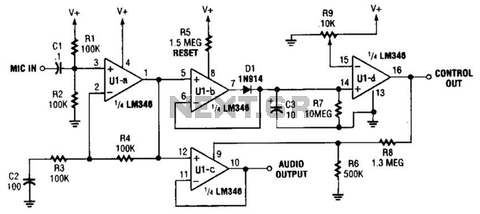
In specific applications, such as transmitters or other communications and control systems, this circuit is designed to be beneficial. It provides both audio output and DC control outputs. Additionally, R9 establishes the control threshold. The circuit in question is versatile...
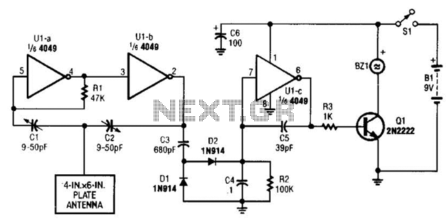
A CMOS logic gate is utilized in this circuit. When an object approaches the antenna, the change in oscillator output is detected by components 1)1 and 1)2, which is then amplified by U1C. This amplification drives Q1, activating alarm...
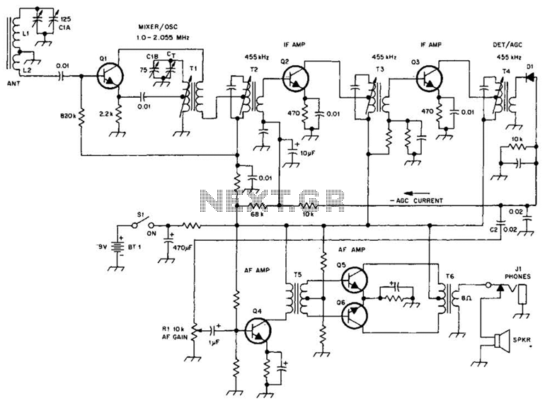
A schematic of a typical transistor AM radio is presented. This circuit utilizes npn transistors. It is a generic circuit; hence, specific values for some components are not provided. This circuit serves as a reference point for experimenters. The schematic...
Warning: include(partials/cookie-banner.php): Failed to open stream: Permission denied in /var/www/html/nextgr/view-circuit.php on line 713
Warning: include(): Failed opening 'partials/cookie-banner.php' for inclusion (include_path='.:/usr/share/php') in /var/www/html/nextgr/view-circuit.php on line 713