
PWM Dimmer/Motor Speed Controller

A brief explanation of PWM is pertinent. As the potentiometer is rotated clockwise, the input voltage increases linearly. Initially, the voltage is low enough that the comparator output generates narrow spikes, activating the MOSFET for brief intervals. This results in a low average current, causing connected LEDs to appear dim or the motor to operate at a reduced speed. As the input voltage from the potentiometer rises, the MOSFET remains on for longer durations, thereby increasing power to the load. The PWM principle is illustrated in Figure 1, where the red trace represents the triangular waveform reference voltage, and the green trace shows the voltage from the potentiometer. When the input voltage surpasses the reference voltage, the MOSFET activates, allowing current to flow to the load. Given the relatively high frequency of approximately 600 Hz, LED flicker is not perceptible; however, an audible tone may be generated by the PWM-controlled motor. The average current through the load is determined by the on-time to off-time ratio; when these durations are equal, the average current is half of what would be drawn with direct current.
The circuit diagram is depicted in Figure 2. U1 serves as the oscillator, generating a triangular waveform. Resistors R4 and R5 establish a half-voltage reference, enabling the op-amps to operate around a 6V center voltage. U2A functions as an amplifier, producing a 10V peak-to-peak triangle wave that is utilized by the comparator U2B. This comparator compares the voltage from the potentiometer with the triangular waveform. At a zero input voltage, the comparator output remains low, keeping the MOSFET off, which represents the zero setting. The reference triangle waveform operates within a range of approximately 1.5V to 9.5V, resulting in a small range at both ends of the potentiometer's rotation where no action occurs. This design is practical, as it allows for a clearly defined off and maximum setting. Due to this range, an industry-standard 0-10V DC control signal can be employed for light level adjustment, compatible with systems like C-BUS and other home automation setups.
For D2, a 1N4004 diode is shown, suitable for dimmer applications. However, for motor speed control, a high-current fast recovery diode, such as the HFA15TB60PBF ultra-fast HEXFRED diode, is recommended. The diode should be rated for at least half the full load current of the motor; the suggested HFA15TB60PBF is rated for 15A continuous, making it suitable for motors drawing up to 30A. While constructing the dimmer on veroboard is feasible, it can be challenging, and errors are easily made. Due to the circuit's current handling capability, thick wires should be used to reinforce the thin tracks, even in PCB versions. A PCB is recommended for this project, measuring 53 x 37 mm, containing all necessary components, including screw terminals. The PCB is double-sided with plated-through holes and solder masks on both sides. A heatsink is required for the MOSFET, unless it is used solely for light loads. Insulation between the MOSFET and heatsink is generally necessary, as the transistor case serves as the drain (PWM output). For high current and potential high-temperature applications, the heatsink may need to be larger than anticipated. Although the MOSFET typically dissipates about 2W at 10A, it can generate significantly more heat if it overheats. Switching MOSFETs may enter thermal runaway if not properly heat-sinked. An IGBT (insulated gate bipolar transistor) may also be used, as they generally do not experience the same thermal runaway issues as MOSFETs. Many MOSFETs (or IGBTs) and fast diodes are available for this application. The IRF540 MOSFET is a suitable choice, rated for 27A, providing a good safety margin. Any switching MOSFET rated at 10A or higher, with a maximum voltage exceeding 20V, is acceptable. The circuit should be connected to an appropriate 12V power supply.
During initial power-up, a 100-ohm safety resistor should be placed in series with the positive supply to limit current in case of wiring errors. The total current drain is approximately 2.5mA with the potentiometer fully off, increasing to 12.5mA when fully on. Most of this current flows through the LED, which is also powered by the PWM supply, allowing for visual confirmation of circuit functionality without a load. It is crucial to ensure the potentiometer is fully counterclockwise (minimum) before applying power. The voltage across the safety resistor should not exceed 0.25V when the potentiometer is at minimum, rising to 1.25V at maximum. If these readings are satisfactory, the safety resistor can be removed, and a load can be installed. High-intensity LED strip lights may draw up to approximately 1.5A each, and this dimmer is capable of driving up to 10 of them, depending on the power supply's capabilities and the size of the MOSFET's heatsink.This is yet another project born of necessity. It`s a simple circuit, but does exactly what it`s designed to do - dim LED lights or control the speed of 12V DC motors. The circuit uses PWM to regulate the effective or average current through the LED array, 12V incandescent lamp (such as a car headlight bulb) or DC motor.
The only difference betwee n the two modes of operation is the addition of a power diode for motor speed control, although a small diode should be used for dimmers too, in case long leads are used which will create an inductive back EMF when the MOSFET switches off. The photo shows what a completed board looks like. Dimensions are 53 x 37mm, so it`s possible to install it into quite small spaces. The parts used are readily available, and many substitutions are available for both the MOSFET and power diode (the latter is only needed for motor speed control).
The opamps should not be substituted, because the ones used were chosen for low power and their ability to swing the output to the negative supply rail. Note that if used as a motor speed controller, there is no feedback, so motor speed will change with load.
For many applications where DC motors are used, constant speed regardless of load is not needed or desirable, but it is up to you to decide if this will suit your needs. First, a description of PWM is warranted. As the pot is rotated clockwise, the input voltage changes linearly with rotation. At first, the voltage is such that the comparator output is just narrow spikes, which turn the MOSFET on for a very short period.
Average current is low, so connected LEDs will be quite dim, or a motor will run (relatively) slowly. As the input voltage coming from the pot increases, the MOSFET is on for longer and longer, so increasing power to the load.
Figure 1 shows how the PWM principle works. The red trace is the triangle wave reference voltage, and the green trace is the voltage from the pot. When the input voltage is greater than the reference voltage, the MOSFET turns on, and current flows in the load.
Because the frequency is relatively high (about 600Hz), we don`t see any flicker from the LEDs, but the tone is audible from a motor that`s PWM controlled. The PWM signal is shown in blue. The average current through the load is determined by the ratio of on-time to off-time, and when both are equal, the average current is exactly half of that which would be drawn with DC.
The circuit is shown in Figure 2. U1 is the oscillator, and generates a triangular waveform. R4 and R5 simply set a half voltage reference, so the opamps can function around a 6V centre voltage. U2A is an amplifier, and its output is a 10V peak to peak triangle wave that is used by the comparator based on U2B.
This circuit compares the voltage from the pot with the triangle wave. If the input voltage is at zero, the comparator`s output remains low, and the MOSFET is off. This is the zero setting. In reality, the reference triangle waveform is from a minimum of about 1. 5V to a maximum of 9. 5V, so there is a small section at each end of the pot`s rotation where nothing happens. This is normal and practical, since we want a well defined off and maximum setting. Because of this range, for lighting applications, an industry standard 0-10V DC control signal can be used to set the light level. C-BUS (as well as many other home automation systems) can provide 0-10V modules that can control the dimmer.
While a 1N4004 diode is shown for D2, this is only suitable if the unit is used as a dimmer. For motor speed control, a high-current fast recovery diode is needed, such as a HFA15TB60PBF ultra-fast HEXFRED diode. There are many possibilities for the diode, so you can use whatever is readily available that has suitable ratings.
The diode should be rated for at least half the full load current of the motor, and the HFA15TB60PBF suggested is good for 15A continuous, so is fine with motors drawing up to 30A. While it`s certainly possible to build the dimmer on veroboard or similar, it`s rather fiddly to make and mistakes are easily made.
Also, be aware that because of the current the circuit can handle, you will need to use thick wires to reinforce some of the thin tracks. This is even necessary for the PCB version. Naturally, I recommend the PCB, and this is available from ESP. The board is small - 53 x 37mm, and it carries everything, including the screw terminals. The PCB is double-sided with plated-through holes, and has solder masks on both sides. The MOSFET will need a heatsink unless you are using the dimmer for light loads only. It is necessary to insulate the MOSFET from the heatsink in most cases, since the case of the transistor is the drain (PWM output).
For use at high current and possible high temperatures, the heatsink may need to be larger than expected. Although the MOSFET should normally only dissipate about 2W or so at 10A, it will dissipate a lot more if it`s allowed to get hot.
Switching MOSFETs will cheerfully go into thermal runaway and self destruct if they have inadequate heatsinking. You may also use an IGBT (insulated gate bipolar transistor) - most should have the same pinouts, and they do not suffer from the same thermal runaway problem as MOSFETs.
As noted above, there are many different MOSFETs (or IGBTs) and fast diodes that are usable. The IRF540 MOSFET is a good choice, and being rated 27A it has a generous safety margin. There are many others that are equally suitable - in fact any switching MOSFET rated at 10A or more, and with a maximum voltage of more than 20V is quite ok. Connect to a suitable 12V power supply. When powering up for the first time, use a 100 ohm "safety" resisor in series with the positive supply to limit the current if you have made a mistake in the wiring.
The total current drain is about 2. 5mA with the pot fully off, rising to 12. 5mA when fully on. Most of this current is in the LED, which is also fed from the PWM supply so you can see that everything is working without having to connect a load. Make sure that the pot is fully anti-clockwise (minimum), and apply power. You should measure no more than 0. 25V across the safety resistor, rising to 1. 25V with the pot at maximum. If satisfactory, remove the safety resistor and install a load. High intensity LED strip lights can draw up to ~1. 5A each, and this dimmer should be able to drive up to 10 of them, depending on the capabilities of the power supply and the size of the heatsink for the MOSFET.
🔗 External reference
Related Circuits
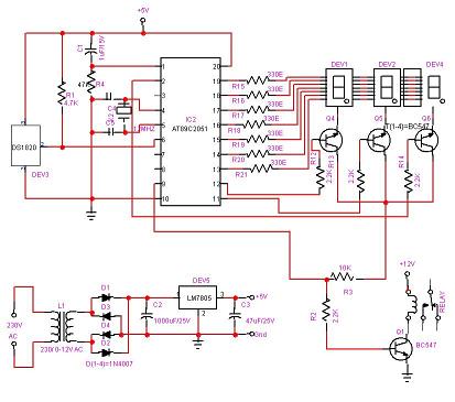
Best Microcontroller Projects. Do you want to learn how to use a microcontroller in your electronic projects, or do you need inspiration for your next project? If so, you have found the right place! Here is a tutorial on...
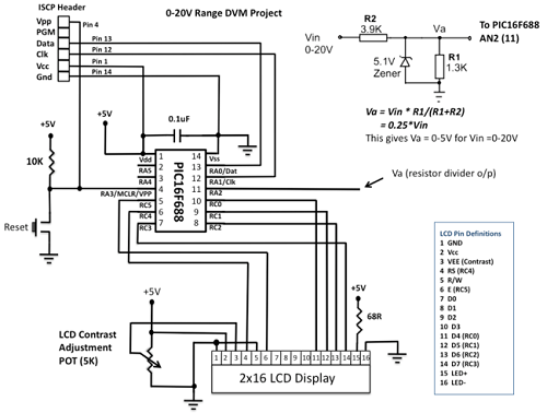
This project details the construction of a digital voltmeter utilizing a PIC microcontroller. A character-based HD44780 LCD display is employed to visualize voltage measurements. The microcontroller selected for this project is the PIC16F688, which features 12 I/O pins, with...
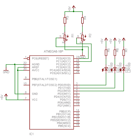
Neural networks are a broad topic. This example demonstrates how to create a basic neural sensor that takes resistive readings from multiple sensors, multiplies them by a weight factor, and then sums the results. The results are compared to...
This temperature controller utilizes an LM135/235/335 temperature sensor and is designed to maintain a small environment at a warm or hot temperature. A schematic diagram is provided. The temperature controller circuit is centered around the LM135/235/335 series of temperature sensors,...
A tiny speedometer/trip computer was constructed using an Atmel ATTiny2313 microcontroller and an HD44780-compatible character LCD display, along with a reed switch and magnets. This device measured the speed of a soapbox derby cart by attaching a permanent magnet...
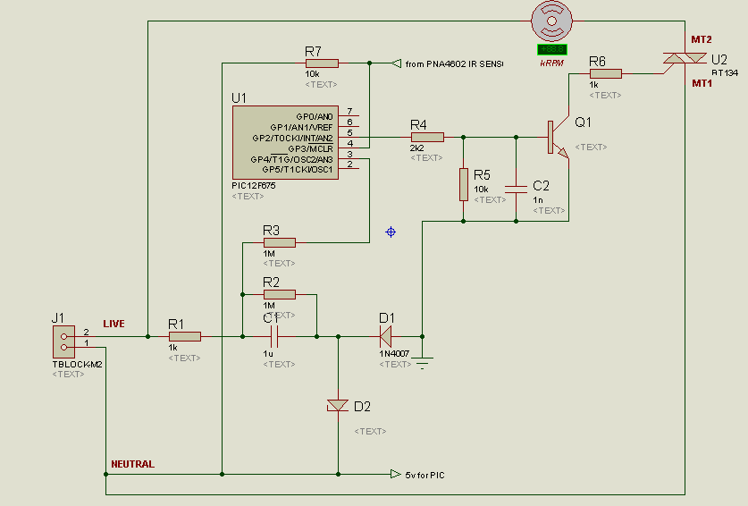
A project is underway to control the speed of an electric fan (220Vac, 60W, 5A max.) automatically using a microcontroller based on certain parameters. The circuit design for controlling the speed of an electric fan involves several key components to...