
vu meter circuit
The VU meter circuit based on the LM3915 chip offers a straightforward solution for visualizing audio signal levels. The LM3915 operates in two modes: dot mode, where only one LED is illuminated at a time, and bar mode, where multiple LEDs light up to indicate the signal level. For this application, the bar mode is typically employed to provide a continuous visual representation of audio levels.
The circuit configuration involves connecting the audio signal to the input pin of the LM3915. The chip's internal reference voltage is calibrated to ensure accurate LED illumination corresponding to specific voltage levels. The trimmer potentiometer allows for fine-tuning the sensitivity of the VU meter, ensuring that the display accurately reflects the desired volume level.
The choice of using 10 LEDs provides a clear and effective way to visualize audio levels, with each LED representing a specific range of voltage levels. The logarithmic scaling of the LM3915 ensures that the human perception of sound intensity is accurately represented, as our ears perceive sound levels logarithmically rather than linearly.
It is crucial to adhere to the power supply requirements, ensuring that the circuit receives a stable 12V supply to function correctly. The placement of the 100nF capacitor close to the power supply pins of the LM3915 is essential for filtering any noise that may affect the performance of the VU meter. The optional electrolytic capacitor serves as an additional filter for longer LED supply leads, ensuring stable operation even at extended distances.
In summary, the LM3915-based VU meter is a simple yet effective tool for monitoring audio levels, suitable for various applications in audio equipment, sound engineering, and visual audio displays. Its ease of construction and reliability make it a popular choice among electronics enthusiasts and professionals alike.This is by far the simplest VUmeter you can build. It is based on a single chip. A volume unit (VU) meter or standard volume indicator is a device for displaying the level of any voltage signal source (which is usually a sound signal). Connect the module to the output of any amplifier (or preamplifier) and set the trimmer where all LEDs are lighti
ng, when the volume of the amp is at maximum (or at least at that point, where you want all LEDs to light). LM3915 is a very powerful and easy to find chip. It`s a monolithic integrated circuit that senses analog voltage levels providing a logarithmic 3 dB/step analog display.
With it, you can drive LEDs, LCDs or even VFDs (Vacuum Fluorescent Displays). In this circuit we use it as a VUmeter, driving 10 LEDs. Each time a new LED is lighting when the input voltage is 1. 41 times the voltage, where the previous LED started to light. This is exactly the point where the voltage is 3dB higher than the previous one. Also you will need a stabilized 12V external power supply. You can power the VUmeter directly from the power source of the amplifier (or preamp) providing the input signal (meaning if the amp is also using a 12V supply). Attention: Make sure you solder the 100nF capacitor as close to LM3915 power supply pins as possible.
The optional electrolytic capacitor is required only if leads to the LED supply are 15cm (about 6 inches) or longer. All 220 © resistors are used to limit LM3915 power dissipation and aren`t optional. 🔗 External reference
Related Circuits
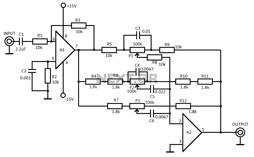
This 3-band equalizer circuit is an active filter network designed to adjust bass, midrange, and treble audio frequencies. It utilizes the LM833 operational amplifier from National Semiconductors, which is known for its very low noise figure and wide frequency...
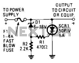
Many modern devices have shutdown circuits that are designed to remove power from the device when the voltage rises above a predetermined threshold. This circuit blows a fuse to protect the device under power. Shutdown circuits are critical components in...
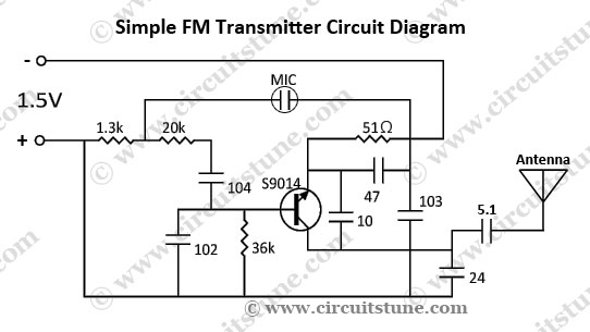
This is a simple FM transmitter circuit schematic diagram that utilizes a single transistor, S9014. The FM transmitter circuit operates by modulating an audio signal onto a carrier frequency, which is typically in the FM band. The S9014 transistor serves...
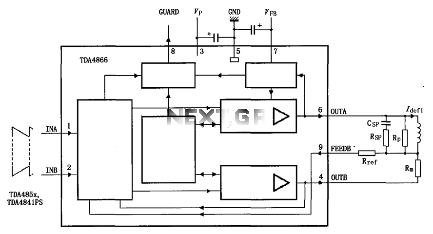
The TDA4866 is a 90-color power amplifier designed for vertical deflection systems, operating at a frequency range of 50 to 160 Hz. The CRMM circuit is implemented to ensure a high current drive input. The amplifier features a dual...
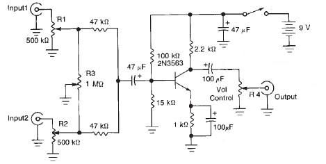
This audio mixer circuit diagram electronic project is designed using a few common electronic components. The audio mixer circuit project has two input channels. The input signal can be independently controlled using the R1 and R2 variable resistors. The...
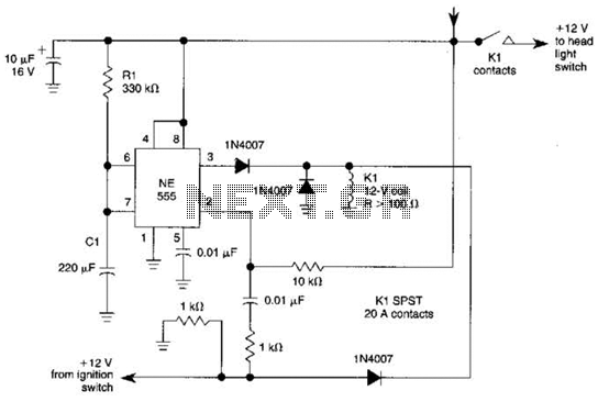
When the ignition switch is activated, relay K1 receives continuous power, allowing the headlights to be turned on. When the ignition is turned off, timer IC1 is activated, maintaining its power for a duration determined by resistor R1 and...