
Head light timer circuit
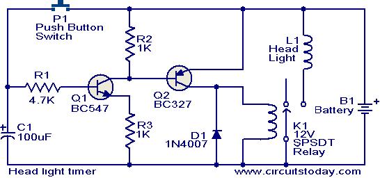
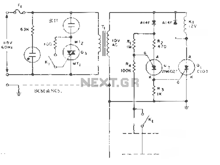
The timer circuit for car headlights employs a straightforward yet effective design that integrates discrete components to manage the lighting duration. The circuit begins with a power source, typically the vehicle's battery, supplying voltage to the system. The push button switch P1 serves as a manual trigger. Upon activation, it allows current to flow into the capacitor C1, initiating its charging process. The choice of C1's capacitance value is crucial, as it directly influences the timing characteristics of the circuit.
Transistor Q1 operates as a switch, controlling the flow of current to the next stage. When C1 reaches the battery voltage, Q1 turns on, creating a path for current to flow to transistor Q2. The activation of Q2 subsequently energizes relay K1, which is responsible for connecting the headlights to the power supply, thereby illuminating them.
The relay is an electromechanical switch that maintains its state while C1 discharges through resistor R1. The discharge rate, determined by the RC time constant (τ = R1 * C1), dictates how long the headlights remain on. For a delay of 1.5 minutes, appropriate values for R1 and C1 must be selected, ensuring that the circuit functions effectively within the desired time frame.
Once the capacitor C1 discharges below a certain threshold, transistor Q1 turns off, which in turn deactivates Q2 and opens the relay K1, cutting off power to the headlights. This automatic shut-off feature is particularly beneficial for preventing battery drain when the vehicle is parked in low-light conditions.
Overall, this compact timer circuit enhances vehicle functionality by providing convenience and ensuring that headlights are not left on inadvertently, thus contributing to a more user-friendly driving experience.This circuit is a compact timer circuit that will keep the headlights of your car ON for about 1. 5 minutes and then turns it OFF. This circuit incorporated to your car will help you to access dark places with out the need to come back and turn OFF the head lights. When the push button switch P1 is pressed the capacitor C1 is charged to the full bat tery voltage. As a result the transistor Q1 is turned ON, which in turns ON Q2 which in turns drives the relay K1 to glow the head lights. The relay K1 will remain activated until the capacitor C1 is fully discharged. The time delay of the circuit depends on values of C1 & R1 and here it is set to be 1. 5 minutes. We aim to transmit more information by carrying articles. Please send us an E-mail to wanghuali@hqew. net within 15 days if we are involved in the problems of article content, copyright or other problems.
We will delete it soon. 🔗 External reference
Related Circuits
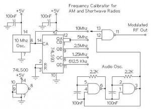
The following circuit illustrates an AM/Shortwave Radio Frequency Calibrator Circuit Diagram. This circuit is based on the 74LS93 IC. Features: The .. The AM/Shortwave Radio Frequency Calibrator Circuit utilizes the 74LS93 integrated circuit, which is a 4-bit binary counter. This...
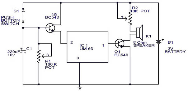
This circuit is a slight modification of a previous design. In the earlier version, the switch needed to be held down for the entire duration of the music playback. In this updated circuit, pressing the push button once charges...
This circuit effectively simulates various light sources such as a house fire, campfire, or welding light without the use of a microcontroller, although it requires a considerable number of components, including some uncommon ones. It is based on three...
This circuit is designed to maintain the liquid level between two fixed points. By transforming the K1 contacts off the case, it can perform filling or extraction operations in two modes. The load can be either an AC motor...
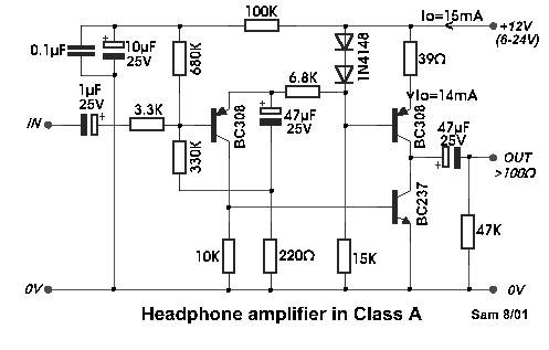
Even if the circuit is simple, it complies with all conditions regarding distortion and frequency response. The input resistance is 250K ohms, and it can drive loads ranging from 100 ohms to 2K ohms. The described circuit is a fundamental...

This circuit utilizes three readily available 555 timer integrated circuits (ICs), all functioning as astable multivibrators. The first 555 timer has both an on period and an off period of 1 second. This IC regulates the on/off intervals of...
Warning: include(partials/cookie-banner.php): Failed to open stream: Permission denied in /var/www/html/nextgr/view-circuit.php on line 713
Warning: include(): Failed opening 'partials/cookie-banner.php' for inclusion (include_path='.:/usr/share/php') in /var/www/html/nextgr/view-circuit.php on line 713