
alternating flasher circuit diagram

The circuit design incorporates three 555 timer ICs, configured as astable multivibrators to create a flashing light effect. The primary 555 timer is responsible for generating a square wave signal with a frequency of 4 Hz, resulting in an on/off cycle of 1 second. This output controls the timing of the second and third 555 timers, which are set to the same frequency, ensuring synchronized operation.
The first 555 timer is connected in a standard astable configuration, with resistors and capacitors selected to achieve the desired timing intervals. The output pin of this timer drives the base of a transistor, which in turn controls the relay that powers the first bulb. The use of diodes across the relay coils is crucial for protecting the 555 ICs from back EMF generated when the relays are de-energized.
The second 555 timer is similarly configured and is activated by the output of the first timer. It controls a second relay, which operates the second bulb. Both relays must be chosen with care, ensuring that their impedance is greater than 50 ohms to limit current draw to under 200 mA, thus protecting the circuit components from overheating and damage.
This circuit can be effectively used in various applications requiring flashing lights, such as decorative lighting, indicators, or alarms. The repeating cycle of flashing is achieved through the continuous operation of the 555 timers, which maintain a consistent output without the need for additional control circuitry. Overall, this design exemplifies a straightforward yet effective use of timer ICs in creating a visually engaging light display.This circuit uses three easily available 555 timer ICs. All three work as astable multivibrators. The first 555 has an on period and off period equal to 1 sec. This IC controls the on/ off periods of the other 2 555s which are used to flash two bulbs through the relay contacts. The diodes are used to protect the 555 ICs from peaks. The relays shou ld have an impedance greater than 50ohms i. e, they should not draw a current more than 200mA. The bulb(s) connected to the first relay flashes for about 1 sec at a rate of 4 flashes per second. Then the bulb(s) connected to the second relay flashes for 1 sec at a rate of 4 flashes per second. Then the cycle repeats. Disclaimer: All the information present on this site are for personal use only. No commercial use is permitted without the prior permission from authors of this website. All content on this site is provided as is and without any guarantee on any kind, implied or otherwise. We cannot be held responsible for any errors, omissions, or damages arising out of use of information available on this web site.
The content in this site may contain COPYRIGHTED information and should not be reproduced in any way without prior permission from the authors. 🔗 External reference
Related Circuits
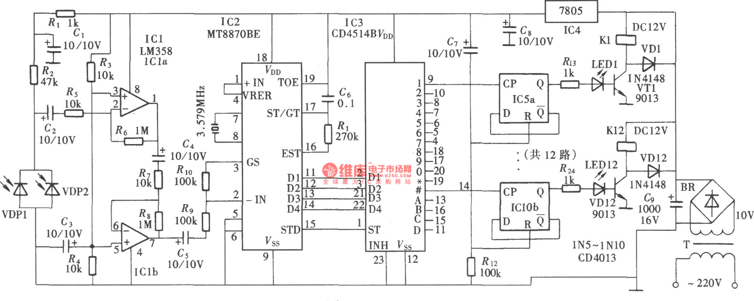
The DTMF codec stands for dual-tone multi-frequency codec. The multiple-channel infrared remote control switch circuit that incorporates the DTMF is depicted in the figure. It consists of an infrared remote control signal emitter, an infrared receiving signal amplifier, a...
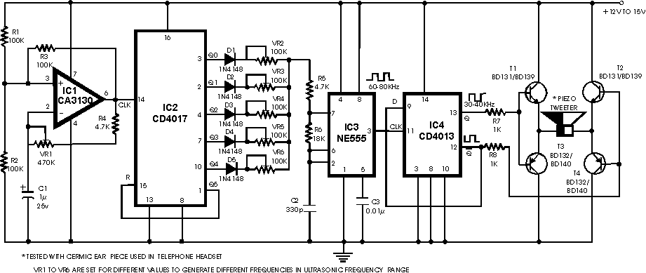
A circuit diagram for an animal repeller is provided. The circuit has been developed but is not functioning as intended. Assistance is requested for troubleshooting. The animal repeller circuit typically employs ultrasonic sound waves to deter animals from specific areas....
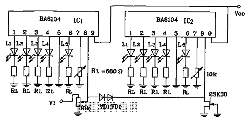
BA6104 is a five-digit LED level meter that functions as an LED display driver integrated circuit (IC). The configuration of the circuit is illustrated in the accompanying figure. The circuit utilizes a 10 by two-dot LED level display. The...
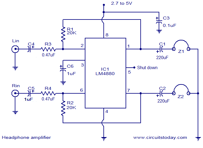
The LM4880 is a high-fidelity dual audio amplifier integrated circuit (IC) from National Semiconductors. This IC is specifically designed to deliver high-quality audio output with a minimal number of external components. The LM4880 can provide 250mW per channel into...
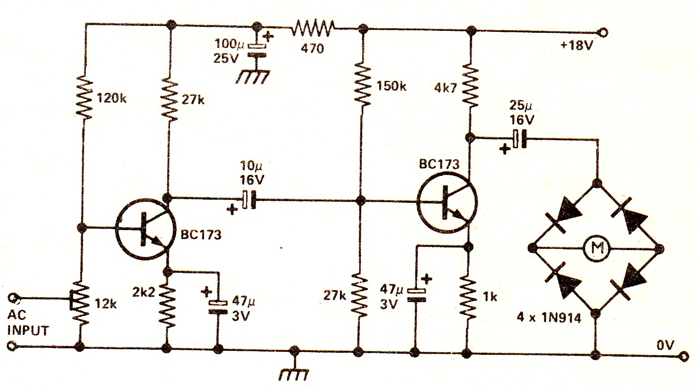
The circuit illustrates a two-stage voltage amplifier that drives a recording level meter. An AC signal input is amplified and rectified, with the resulting DC voltage displayed on the meter. This circuit is compatible with tape recorders or audio...
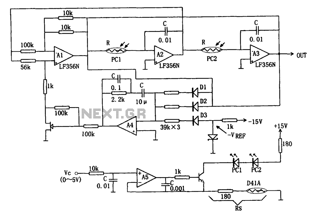
The wideband sinusoidal voltage-controlled oscillator circuit is designed such that the oscillation frequency is determined by an integrating resistor R and a capacitor C. The voltage-controlled oscillator is constituted by the applied control voltage Vc and a control resistor...
Warning: include(partials/cookie-banner.php): Failed to open stream: Permission denied in /var/www/html/nextgr/view-circuit.php on line 713
Warning: include(): Failed opening 'partials/cookie-banner.php' for inclusion (include_path='.:/usr/share/php') in /var/www/html/nextgr/view-circuit.php on line 713