
Flickering Light II
The described circuit utilizes unijunction transistors to create a visually engaging flickering light effect, suitable for simulating various scenarios. The three oscillators, each tuned to different frequencies, generate pulse signals that are mixed to produce the desired flickering. The use of a triac optocoupler allows for effective control of the light output while maintaining safety and isolation from the high-voltage components. The inclusion of a zero-voltage switching mechanism enhances the realism of the flickering effect, making it particularly suitable for applications in model railroading or theatrical displays. The ability to vary the flickering pattern through a Hall effect switch provides an additional layer of dynamism, effectively mimicking the unpredictable nature of fire or welding light. Overall, this circuit exemplifies a creative approach to electronic design, leveraging a combination of basic components to achieve a complex and visually appealing output.Regardless of whether you want to effectively imitate a house fire, a campfire, or light from welding, the circuit described here fills the bill without using a microcontroller, although it does use a larger number of components (including some truly uncommon ones). The circuit is based on three oscillators, which are built using unijunction trans istors (UJTs). Each oscillator has a different frequency. The output voltages are mixed, which produces the flickering effect. A unijunction transistor consists of an n-type bar of silicon between two ohmic (non-barrier) base contacts (B1 and B2). The effective resistance is controlled by the p-type emitter region. The designation transistor` is a somewhat unfortunate choice, since it cannot be used for linear amplification.
UJTs are suitable for use as pulse generators, monostable multivibrators, trigger elements and pulse-width modulators. If a positive voltage is applied to the emitter (E), the capacitor charges via the resistor. As soon as the voltage on the emitter reaches approximately half the supply voltage (for a 2N2645, the value lies in the range of 56 75 %), the UJT fires` and the capacitor discharges via base B1 and the resistor, generating a positive pulse.
The UJT then returns to the non-conduct state, and the process just described repeats periodically. The frequency can be approximately given by the formula f 1/(RC) The frequency is independent of the value of the supply voltage (which must not exceed 35 V). The maximum emitter blocking voltage is 30 V, and the maximum permissible emitter current is 50 mA. The values of resistors R1, R2 and R3 can lie between 3 k and 500 k. If necessary, the frequency can be varied over a range of 100:1 by using a trimpot instead of a fixed resistor.
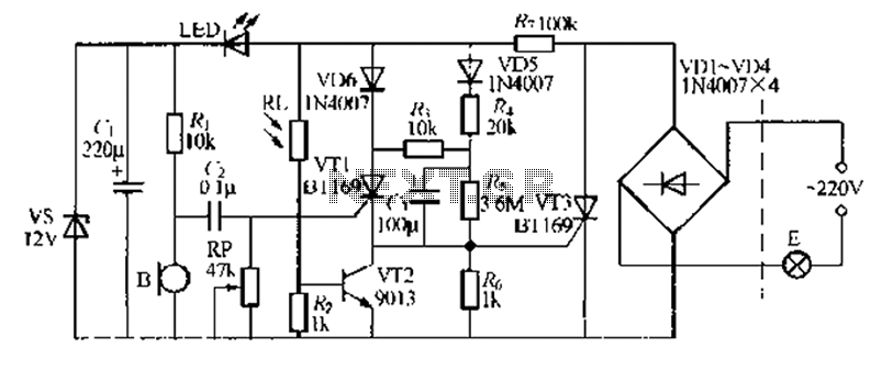
The frequencies from the three pulse generators are mixed by connecting them to the IR diode of a triac optocoupler via R4. The optocoupler, a type MOC3020, K3030P or MCP3020, can handle a maximum load current of 100 mA. The triac triggers at irregular intervals and generates the desired flickering light in the two small lamps, L1 and L2, which are connected in series to the transformer secondary.
The light effect can be noticeably improved by using a MOC3040, which contains a zero-voltage switch, since its generates irregular pauses of various lengths when suitable frequencies occur in the individual oscillators. The zero-voltage switch does not switch while the current is flowing, but only when the applied ac voltage passes through zero.
An integrated drive circuit (zero crossing unit) allows full half-waves or full cycles to pass (pulse-burst control) Due to the flickering effect arising from its switching behaviour, it is not suitable for normal lighting, but here this just what we want. This version of the optocoupler is also designed for a maximum current of 100 mA. For a small roof fire or the light of a welding torch in a workshop, two small incandescent lamps connected in series and rated at 6 V / 0.
6 A (bicycle taillight bulbs) or a single 12-V lamp (rated at 100 mA) is adequate. If it is desired to simulate a large fire, a triac (TIC206D, rated at 400 V / 4 A, with a trigger current of 5 mA) can be connected to the output of the circuit and used to control a more powerful incandescent lamp. As continuous flickering looses its attraction for an interested observer after a while (since no house burns for ever, and welders also take breaks), it`s a good idea to vary the on and off times of the circuit.
This is handled by a bipolar Hall switch (TLE4935L), which has such a small package that it can fitted between the sleepers of all model railway gauges, including Miniclub (Z Gauge), or even placed alongside the track if a strong permanent magnet is used. If a magnet is fixed somewhere on the base of a locomotive such that the south pole points toward the package of the Hall switch (the flattened front face with the type marking), the integrated npn transistor will switch on and pull the base of the external pnp transistor negative, causing the collector emitter junction to conduct and provide the necessary juice` for the unijunction transistors.
If another traction unit whose magnet has it s north pole pointing toward the Hall switch passes a while later, the switch will be cut off and the flickering light will go out. Of course, you can also do without this form of triggering and operate the device manually. 🔗 External reference
Related Circuits

This light alarm schematic circuit is designed using common electronic components, as illustrated in the circuit diagram below. The light alarm circuit will activate an alarm as soon as the drawer is opened and light falls on the Darlington...
A useful operation for the cars is delayed extinguishing internal lighting cabin of passengers, after close some door of car. Certain cars allocate this operation from their constructor. Oldest sure do not allocate such operation. This delay makes this...
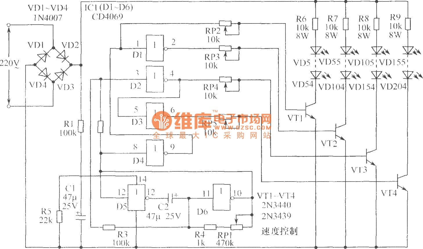
The chart illustrates a Christmas lights circuit that employs a simple and cost-effective CD4069 CMOS hex inverter to control four separate circuits, each consisting of 50 light-emitting diodes (LEDs), totaling 200 LEDs. The circuit is powered directly by a...
A relatively simple circuit for controlling a stair walkway light with a delay feature. The circuit has a drawback in that the voice activation is somewhat less sensitive, making it sometimes difficult to trigger with general conversation. However, it...
This device is a simple timer that keeps the headlights of a vehicle on for approximately 1 minute and 30 seconds, allowing for illumination when accessing dark areas without the need to return to switch off the lights. Pressing...
LEDs lining the headliner will fade in when the door is opened and fade out when the door is closed. The necessary components include a circuit to utilize 12V power from the vehicle to illuminate 15 LEDs and control...
Warning: include(partials/cookie-banner.php): Failed to open stream: Permission denied in /var/www/html/nextgr/view-circuit.php on line 713
Warning: include(): Failed opening 'partials/cookie-banner.php' for inclusion (include_path='.:/usr/share/php') in /var/www/html/nextgr/view-circuit.php on line 713