
Headlight delay unit
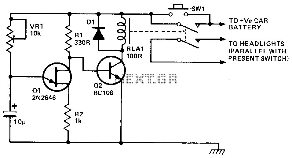
This circuit employs a simple timer mechanism utilizing a relay, transistors, and a capacitor to manage the operation of the car's headlights post-exit. The primary components include a relay for controlling the high-current headlights, and two transistors (Q1 and Q2) that function as electronic switches.
When the driver exits the vehicle and presses the switch SQ1, it triggers Q2, allowing current to flow through the relay coil. This energizes the relay, which closes its contacts and connects the car's headlights to the power supply, thereby illuminating the area. The use of a relay is crucial here, as it can handle the higher current required by the headlights without putting excessive load on the transistors.
Capacitor C1 plays a pivotal role in the timing aspect of the circuit. Initially, when SQ1 is pressed, C1 begins to charge through the variable resistor VR1, which allows for adjustment of the delay duration. The charging time of C1 determines how long the headlights remain on after the relay is activated. Once C1 reaches a certain voltage threshold, it activates Q1. This, in turn, turns off Q2, de-energizing the relay and opening its contacts, thus cutting power to the headlights.
The design allows for a customizable delay through the adjustment of VR1, making it adaptable to various user preferences. The circuit is efficient and reliable, providing a practical solution for enhancing safety and convenience when exiting a vehicle at night. Proper consideration should be given to the ratings of the components, particularly the relay and transistors, to ensure they can handle the expected load and operate within safe limits.This circuit will operate a car"s headlights for a predetermined time to light up the driveway or path after the driver has left the car. SQl is pushed and Q2 is turned on closing the relay and turning on the car"s headlights. Cl begins to charge through VR1 until Q1 turns on, turning Q2 off The relay will then open switching off both the lights and the unit. The delay is governed by the time taken for the capacitor to charge, which is about one minute. 🔗 External reference
Related Circuits
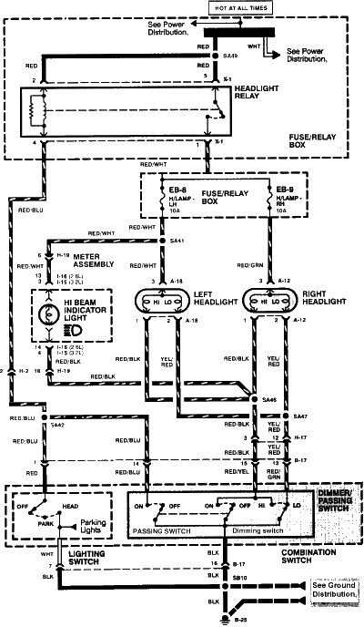
1996 Isuzu Rodeo Headlight Wiring Diagram. The 1996 Isuzu Rodeo headlight wiring diagram provides a detailed representation of the electrical connections and components involved in the vehicle's headlight system. This diagram is essential for understanding how the headlight assembly operates...
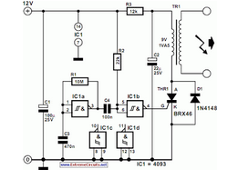
This circuit is a thyristor-based delay circuit known as a cut-off delay. It allows for a specified delay period after the thyristor is activated. The delay time of the circuit can be adjusted within 10 seconds by changing the...
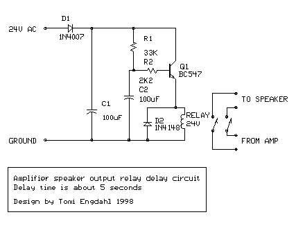
The following circuit illustrates a BC547 transistor used in an output relay delay audio amplifier circuit diagram. Features include the immediate disconnection of the speaker when the... The BC547 transistor is a widely utilized NPN bipolar junction transistor, often employed...
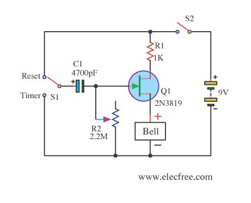
This circuit utilizes the FET 2N3819, which functions as a switch, operating in both conduction and non-conduction states. This behavior is in contrast to that of a bipolar transistor. The 2N3819 is a Junction Field Effect Transistor (JFET) known for...
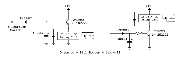
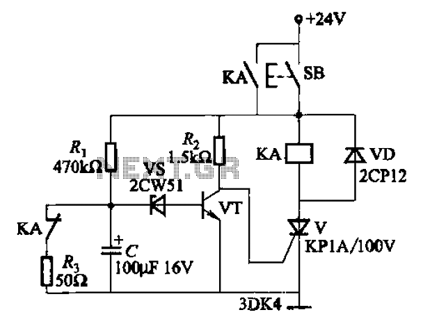
The two circuits below illustrate opening a relay contact a short time after the ignition or light switch is turned off. The capacitor is charged and the relay is closed when the voltage at the diode anode rises to...
The circuit is designed for conducting safe experiments with high-voltage pulses and operates similarly to an electrified fence generator. This circuit is engineered to generate high-voltage pulses suitable for educational purposes and experimentation. The design is inspired by electrified fence...
Warning: include(partials/cookie-banner.php): Failed to open stream: Permission denied in /var/www/html/nextgr/view-circuit.php on line 713
Warning: include(): Failed opening 'partials/cookie-banner.php' for inclusion (include_path='.:/usr/share/php') in /var/www/html/nextgr/view-circuit.php on line 713