
10 minute time delay by fet 2n3819

The 2N3819 is a Junction Field Effect Transistor (JFET) known for its high input impedance and low noise characteristics, making it suitable for various switching applications. In this circuit, the FET operates by controlling the flow of current through its channel based on the voltage applied to its gate terminal. When a sufficient voltage is applied to the gate, the FET enters the conduction state, allowing current to flow from the drain to the source. Conversely, when the gate voltage is removed or reduced below a certain threshold, the FET switches to the non-conduction state, effectively interrupting the flow of current.
The circuit typically includes a resistor connected to the gate to establish the necessary biasing conditions. The drain is connected to the load, which could be any device requiring control, such as an LED or a relay. The source is usually connected to ground or a common reference point in the circuit.
In practical applications, the 2N3819 can be employed in digital switching circuits, amplifiers, and signal modulation systems. Its ability to switch rapidly and operate efficiently makes it a valuable component in modern electronic designs. Additionally, it is important to consider the maximum ratings specified in the datasheet for the 2N3819, including gate-source voltage, drain current, and power dissipation, to ensure reliable operation within safe limits.
Overall, the 2N3819 serves as a versatile switch in electronic circuits, demonstrating unique characteristics that distinguish it from traditional bipolar transistors.This circuit is a basic function of the FET 2N3819, which acts as a switch. In the conduction and not conduction. It runs contrary to the transistor. The.. 🔗 External reference
Related Circuits
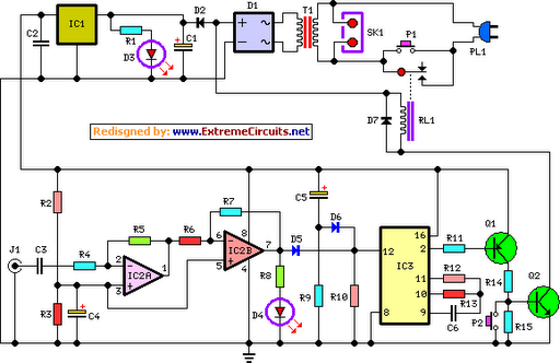
This circuit deactivates an amplifier or any connected device when a low-level audio signal is absent at its input for at least 15 minutes. Activating switch P1 powers the device, enabling operation of any appliance connected to SK1. The...
This is a voltage doubling circuit built using the well-known timer IC 555. The circuit is straightforward and easy to construct. The construction is not critical. Rectifier diodes should be ultrafast (such as UF4004 or similar), or 1N4148 signal...
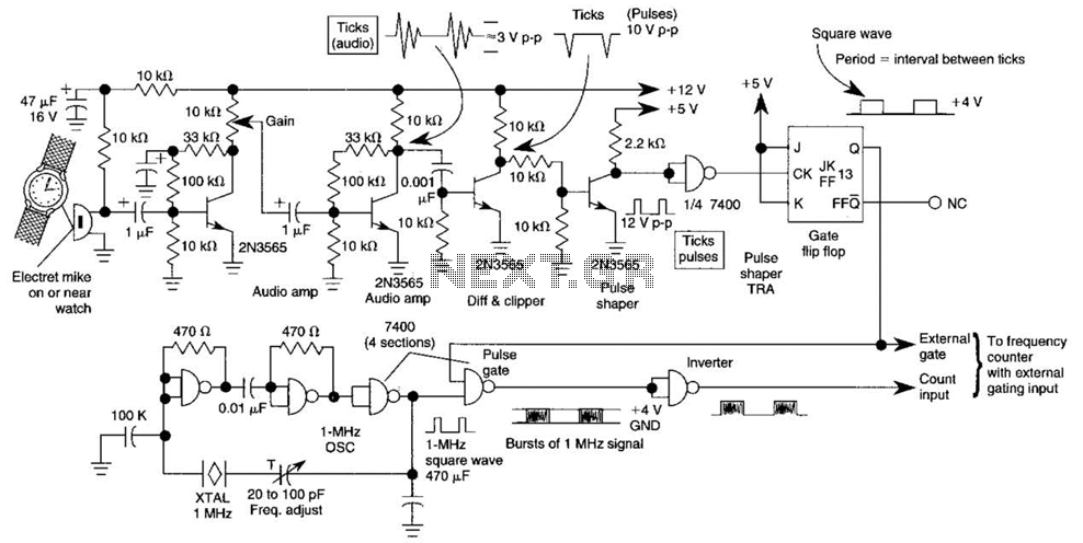
This circuit adapts a frequency counter to measure intervals. It was originally utilized as a shutter speed checker for photographic applications. The watch ticks are clipped, shaped, and formed into a square wave. This square wave is employed to...
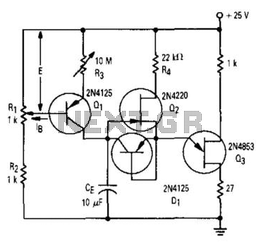
Transistor Q1 and resistors R1, R2, and R3 form a constant current source, with the charge current adjustable to as low as a few nanoamperes. This current is insufficient to activate the UJT, where IP is 0.2 A, unless...
The objective of this circuit is to power a lamp or other device for a predetermined duration (30 minutes in this instance) and subsequently turn it off. This functionality is particularly beneficial for reading in bed at night, as...
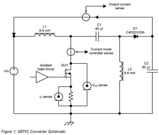
Comparing the performance of 1200V silicon carbide (SiC) MOSFETs with 1200V silicon MOSFETs and IGBTs at high frequency is essential to identify the differences in device losses and power-handling capabilities among these technologies. A demonstration platform has been developed...