
Power Off Delay Relay circuits
The described circuits are designed to control a relay's operation based on the ignition or light switch status. The first circuit, utilizing a common collector configuration, simplifies the design by eliminating the need for a series resistor with the transistor base. However, this results in a reduced voltage across the relay coil due to the inherent voltage drop across the diodes. Specifically, with a supply voltage of 12.5 volts, the relay coil receives approximately 11 volts, which may affect its performance during operation.
In contrast, the second circuit employs a common emitter configuration, which allows for the full supply voltage to be applied across the relay coil for the majority of the delay period. This configuration enhances the reliability of the relay's operation, as it mitigates concerns regarding pull-in and drop-out voltage levels. The inclusion of a series resistor with the transistor base enables the user to fine-tune the delay time by adjusting the resistor value, offering flexibility in design.
The time delay for the common emitter circuit can be calculated using the formula for time constants, expressed as 3 times the product of the resistance (R) and capacitance (C). For practical implementation, the relay coil specifications and the transistor's current gain are crucial parameters in determining the appropriate resistor and capacitor values. For instance, with a relay coil resistance of 120 ohms drawing 100 mA at 12 volts, and assuming a transistor gain of 30, the required base current is calculated to be 3 mA. Consequently, the voltage across the base resistor is derived from the supply voltage minus the voltage drop across the diodes, yielding approximately 10.6 volts. This leads to the calculation of the resistor value at approximately 3.6K ohms.
To achieve a desired delay of 15 seconds, the capacitor value can be computed using the time constant formula. The calculations indicate a need for a capacitor of approximately 1327 microfarads. A standard capacitor of 1000 microfarads can be utilized, with a proportional increase in the resistor value to meet the delay requirement. This setup ensures that the relay operates effectively within the specified time frame, providing a reliable solution for controlling the relay based on the ignition or light switch status.The two circuits below illustrate opening a relay contact a short time after the ignition or ligh switch is turned off. The capacitor is charged and the relay is closed when the voltage at the diode anode rises to +12 volts.
The circuit on the left is a common collector or emitter follower and has the advantage of one less part since a resistor is not needed in series with the transistor base. However the voltage across the relay coil will be two diode drops less than the supply voltage, or about 11 volts for a 12.5 volt input.
The common emitter configuration on the right offers the advantage of the full supply voltage across the load for most of the delay time, which makes the relay pull-in and drop-out voltages less of a concern but requires an extra resistor in series with transistor base. The common emitter (circuit on the right) is the better circuit since the series base resistor can be selected to obtain the desired delay time whereas the capacitor must be selected for the common collector (or an additional resistor used in parallel with the capacitor).
The time delay for the common emitter will be approximately 3 time constants or 3*R*C. The capacitor/resistor values can be worked out from the relay coil current and transistor gain. For example a 120 ohm relay coil will draw 100 mA at 12 volts and assumming a transistor gain of 30, the base current will be 100/30 = 3 mA. The voltage across the resistor will be the supply voltage minus two diode drops or 12-1.4 = 10.6. The resistor value will be the voltage/current = 10.6/0.003 = 3533 or about 3.6K. The capacitor value for a 15 second delay will be 15/3R = 1327 uF. We can use a standard 1000 uF capacitor and increase the resistor proportionally to get 15 seconds. 🔗 External reference
Related Circuits
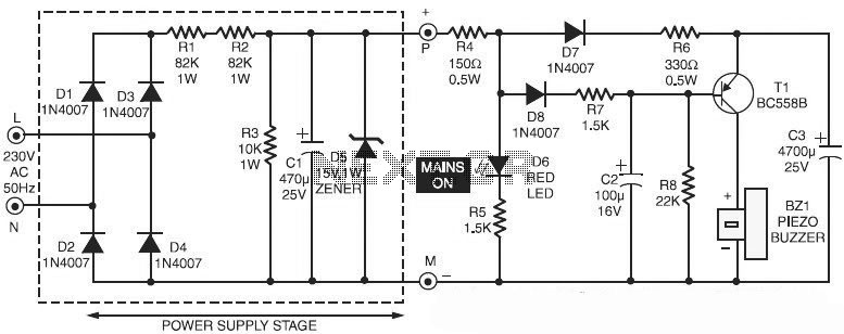
This is a specialized circuit design for a power supply failure alarm. Most power supply failure alarm or indicator circuits require an independent power supply. However, the alarm circuit presented here... The power supply failure alarm circuit is designed to...
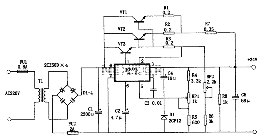
The circuit illustrated in the figure is a +24V, 1.9A power supply design. It employs the 5G14D domestic integrated voltage regulator as the core component, supported by three external power transistors. While the 5G14D voltage regulator has a rated...
This page outlines the development of electronics for displaying a monochrome video image on an electrostatic oscilloscope tube. This work complements the Electron Optics section in the Experiments category. The primary objective is to showcase a moving video image...
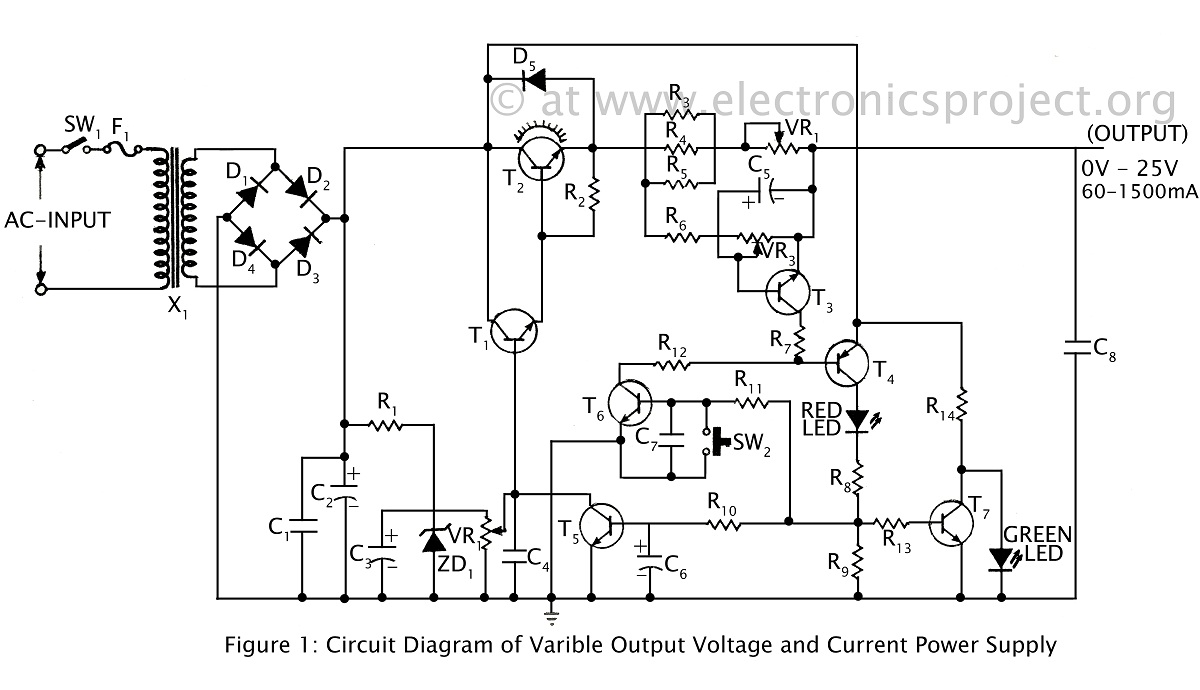
A ripple-free, short-circuit protected variable output voltage and current power supply is presented on this website as a verified project. The circuit diagram includes a description of various power supply circuits. This power supply circuit is designed to provide a...
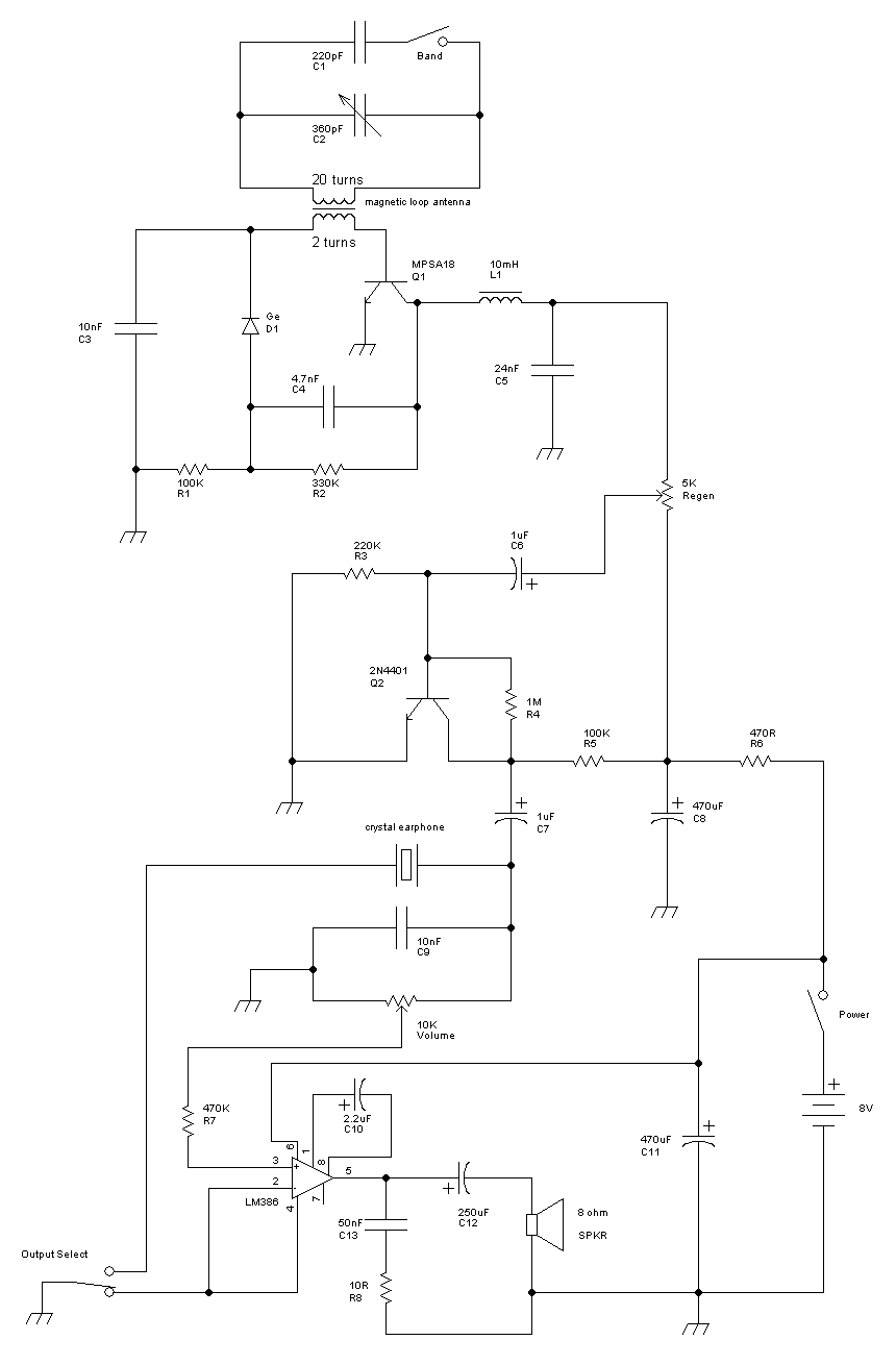
This receiver is a modification of Charles Wenzel's Two Transistor Reflex Radio. Instead of a ferrite AM loopstick antenna, a magnetic loop antenna is used, and an LM386 amplifier stage has been added to drive an 8-ohm speaker. A...
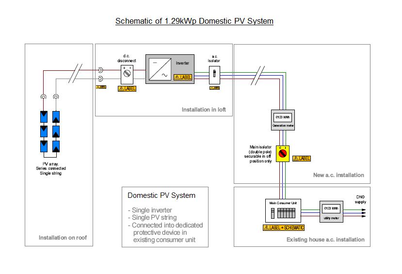
The intention is to genuinely and measurably reduce energy consumption and/or micro-generate energy, leading to a net reduction in the energy imported to a residence each year. Since 2007/2008, all office lighting has been transitioned off-grid, achieving a zero-carbon...