
Headphone Amplifier
The described amplifier circuit utilizes an operational amplifier (op-amp) configuration to achieve significant power output suitable for driving headphones. The output power ratings indicate that the amplifier can deliver approximately 1.5W into an 8-ohm load and 2.2W into a 32-ohm load, which are substantial figures for headphone applications. This high output capability suggests the design is robust, allowing for dynamic audio performance without distortion, which is critical for high-fidelity sound reproduction.
A 120-ohm output resistor is recommended for the circuit, aligning with standard practices for headphone impedance matching. This resistor serves to stabilize the output and ensure that the amplifier operates within the desired parameters. However, it is noted that many headphones perform better when connected to a low impedance source, indicating that users may need to consider their specific headphone characteristics when integrating this amplifier.
The core of the amplifier is based on an op-amp, which is known for its high gain and low distortion properties. The op-amp's output is further enhanced by a pair of transistors that serve to boost the current output. This configuration allows the circuit to handle varying loads effectively while maintaining audio quality. The low distortion levels reported suggest that the amplifier can operate cleanly across its output range, with distortion levels remaining below the measurement threshold, even as the output approaches clipping.
Additionally, the noise performance of the amplifier is highlighted as virtually non-existent, indicating a well-designed circuit that minimizes unwanted audio artifacts. This is particularly important when driving sensitive components like compression drivers, where noise can significantly impact audio clarity and overall performance.
In summary, the amplifier circuit is designed to deliver high power output with low distortion and noise, making it suitable for a range of headphone applications while considering impedance matching for optimal performance.The amplifier is capable of delivering around 1.5W into 8 ohm headphones, and 2.2W into 32 ohms - this is vastly more than will ever be needed in practice. The use of a 120 Ohm output resistor is recommended, as this is supposed to be the standard source impedance for headphones.
Unfortunately, many users have found that their `phones perform better when driven from a low impedance source. The circuit is based on an opamp, with its output current boosted by a pair of transistors. Distortion is well below my measurement threshold at all levels below clipping into any impedance. Noise is virtually non-existent - even with a compression driver 🔗 External reference
Related Circuits
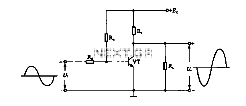
A DC-coupled single-tube amplifier is a circuit that utilizes a single transistor to amplify DC signals. This configuration primarily consists of a transistor, bias resistors, and minimal coupling capacitors. The absence of coupling capacitors allows the DC operating states...
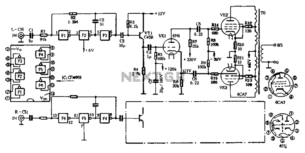
The CD4069 unit structure depicted in Figure 2-5 (a) consists of two abutment surfaces incorporated into a CMOSFET configuration. The input-output characteristics are illustrated in Figure 2-5 (b). Due to its superior unit switching curve, the CD4069 can be...
This circuit provides 16 watts of amplification. It is built using two LM383 power audio amplifiers. Use suitable heat sinks with the ICs. More: U1 U2 LM383 8 watt audio amplifier IC R1, R3 220 ohm resistor R2, R4...
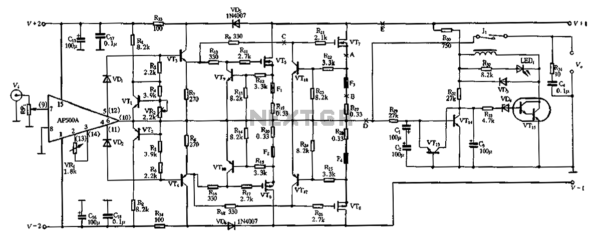
The CPI is a 100W DC super power amplifier circuit based on the AP500. It features a parallel push-pull amplifier output stage composed of transistors VT5, VT6, and VT7 to enhance output power. The circuit's output power is low...
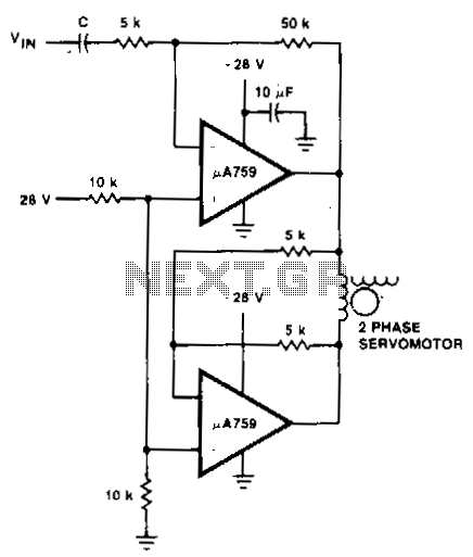
This motor driver circuit utilizes a p.A759 power amplifier to drive a two-phase servomotor. The motor driver circuit is designed to efficiently control a two-phase servomotor, leveraging the capabilities of the p.A759 power amplifier. This amplifier is specifically chosen for...
The objective of this design was to create a combo amplifier reminiscent of those commonly found in the 1960s and 1970s. This amplifier is particularly suitable for guitar applications but can also effectively amplify any electronic musical instrument or...
Warning: include(partials/cookie-banner.php): Failed to open stream: Permission denied in /var/www/html/nextgr/view-circuit.php on line 713
Warning: include(): Failed opening 'partials/cookie-banner.php' for inclusion (include_path='.:/usr/share/php') in /var/www/html/nextgr/view-circuit.php on line 713