
Headphone Amplifier circuits
To reduce this type of distortion, choose a bipolar-input opamp with a wide open-loop bandwidth (into the kHz range) or use a FET-input opamp. FET input stages are more linear and so less susceptible to this type of distortion. Finally, the open-loop bandwidth of the voltage-gain input stage can be effectively extended with local feedback (see the section on output stages below).
Also look for unity gain stability and low offset voltage. Opamps that are internally compensated are less likely to oscillate at high frequencies, and save the builder the hassle of adding external compensation (however, it never hurts to check the amplifier output on an oscilloscope anyway.) The ideal opamp has zero DC output at idle, so that DC coupling can be accomplished without trimming. Real-world opamps have a small output voltage at idle. If the opamp is not followed by a gain stage, a 15mV or less offset at idle should be acceptable. FET-input opamps are known for their low offset voltages. Opamp-based headphone amplifiers can be prone to thermal errors due to output loading of the opamps. The power dissipation in an opamp when driving low impedance loads can raise the temperature of the device and cause changes in the input offset voltage, thus compromising the linearity. In dual and quad IC devices, the thermal conditions of one opamp can affect all others in the package because the opamp circuits share a common substrate ("power-dissipation-related crosstalk").
Thermal errors can be measured by comparing the output distortion of an opamp under load and no-load conditions. Figure 1d shows the thermal loading effect of one buffer on the other in a dual buffer IC (the system circuit is similar to figure 5d). Channel A is being fed a frequency sweep signal; channel B is idle. When buffer A is driving a 25 ohm load (as opposed to driving no load), it induces a stronger thermal-related error signal at the input of buffer B.
When the dual (or quad) IC buffers are used in circuits with voltage gain front-end as seen in figure 5d, these thermal errors can be corrected via global feedback. Conversely, buffering an input-stage opamp can reduce thermal errors in the input stage by isolating the power dissipation to the output stages. (For more information about buffering, see the section on output stages below.) In general, using single opamps instead of duals or quads will prevent power-dissipation crosstalk distortion. Precision low-noise opamps appear to have the lowest thermal errors. Unlike transistor amplifier design, tube amplifier design is more dependent on the electrical characteristics of the tubes themselves. Tube opamps attempt to bring the simplicity and higher performance of amp-block design to tube audio. In audio applications, they can aspire to the same high performance as their solid state cousins and have the additional benefit of even-order distortion harmonics. There has been a revival of interest in these devices with the publication in recent years of several amp-block circuits, ranging from basic AC feedback amplifiers to tube-MOSFET hybrids - all configurable with the familiar opamp feedback scheme.
Not widely available back in the heyday of glass audio, tube opamps are very hard to find today. The following circuits develop the tube amp-block concept with increasing complexity. They all have limited current output and may need an output buffer stage to comfortably drive headphones (see the section on output stages below). To adjust the closed-loop gain of any of these amp-blocks, simply add a feedback resistor from the output to the inverting input and an input resistor - just as with solid state opamps. Some of these amp-blocks may prefer higher magnitudes of resistance than are typical of solid state opamps, so sample gain resistances are included. It's a good idea to construct several of these at a time to have a handy supply for experimentation. Are there audible differences between opamps with similar or identical specs? Some listeners can distinguish between products, but not all. Because modern opamps are internally compensated and are usually plug-in replacements for each other, building circuits with IC sockets or on protoboard first allows the DIYer to audition a variety of opamps at will. Theories abound as to why opamps may have sonic signatures in spite of stellar test results that suggest neutral sound. Years ago, IM, DIM, TIM, etc. distortion were held to be the culprits. Two of the most recent courses of research on this topic have been the effects of the harmonic structure of opamp noise and opamp input errors. Opamp performance specifications are an unreliable indicator of sound quality. So long as the numbers are below audibility thresholds, specs that are magnitudes better than the averages will not necessarily translate into better sound. Regardless of type (bipolar or FET), modern opamps do very well on the test bench. Total harmonic distortion figures are so low (typically less than 0.1%) that datasheets have stopped listing them. Look for noise specifications, listed as "noise density" in units of nV/√(Hz), of 25 or less, slew rates of 5uV/sec or more and "wide" unity gain-bandwidths of 3 MHz and higher.
The design of opamp-based headphone amplifiers involves several critical considerations to ensure optimal performance. The selection of opamps is paramount, as modern opamps are designed to approach ideal characteristics with features such as internal compensation for stability, high slew rates, and low noise and distortion levels. The power supply requirements play a significant role, particularly for portable applications, where the voltage supply can range from ±1.5V to ±9V. It is essential to ensure that the opamp operates within the recommended voltage range to maintain performance levels.
When designing the circuit, the gain-bandwidth product and open-loop bandwidth of the opamp must be analyzed to avoid dynamic phase shifts and non-linear responses at high frequencies. The choice between bipolar-input and FET-input opamps can influence linearity and distortion characteristics, with FET-input opamps generally providing lower offset voltages. Additionally, thermal management must be considered, as thermal errors can arise from output loading, affecting the overall linearity and performance of the amplifier.
The implementation of local feedback can enhance the open-loop bandwidth and mitigate potential distortion. Stability at unity gain is also a crucial factor, particularly in high-frequency applications. The design may incorporate tube opamps, which offer a different sonic character, although they may require additional output stages to drive low-impedance loads effectively.
Overall, careful attention to opamp selection, circuit configuration, and thermal management will lead to the successful design of a headphone amplifier that meets the desired performance specifications.This article discusses several opamp-based headphone amplifier circuits, including suggestions for selecting opamps, input coupling and filtering, high current output stages and power supply options. There are no recommendations for specific opamp brands or models. For tube devotees, there is also an introduction to designing with tube amp-blocks. Tube amp-blocks (AC feedback amplifiers and tube opamps) are not as compact as their silicon brethren, nor do they measure as well, but they do offer smooth tube sound with the ease of feedback configuration.
Entire books cover the subject of interpreting opamp specifications. Here are a few guidelines for choosing opamps when designing headphone amplifiers. Opamps inch closer to the "ideal" with every succeeding generation. Modern devices are internally compensated for stability, have slew rates going through the roof and noise and distortion numbers at threshold of measurement. There are even opamps that will run off a 1-volt supply. For portable devices, the power supply requirements should be the first consideration. The majority of modern opamps will run with as little as ±4V, but low voltages may degrade performance.
Check the manufacturer's VCC specs to confirm that low voltage operation is, in fact, recommended. The most common battery supply voltages are ±1.5V, ±3V, ±4.5V and ±9V. Single supplies are another possibility. Keep in mind also that the idling current for the entire amplifier must also be low - around 10mA or less for good battery life. For more information, see the section on battery power options below. When reviewing the gain-bandwidth specification of a bipolar-input opamp, also examine the open-loop bandwidth.
The gain-bandwidth defines the amount of small-signal gain at any frequency and is the product of the open-loop bandwidth and the open-loop gain. Most opamps have a high open-loop gain (100dB or more) and a relatively narrow open-loop bandwidth (100Hz or less).
In a multi-stage system with overall feedback, if the opamp has a bipolar input stage and narrow open-loop bandwidth, it can manifest dynamic phase shifts and other response non-linearities with high level, high frequency input signals. To reduce this type of distortion, choose a bipolar-input opamp with a wide open-loop bandwidth (into the kHz range) or use a FET-input opamp.
FET input stages are more linear and so less susceptible to this type of distortion. Finally, the open-loop bandwidth of the voltage-gain input stage can be effectively extended with local feedback (see the section on output stages below). Also look for unity gain stability and low offset voltage. Opamps that are internally compensated are less likely to oscillate at high frequencies, and save the builder the hassle of adding external compensation (however, it never hurts to check the amplifier output on an oscilloscope anyway.) The ideal opamp has zero DC output at idle, so that DC coupling can be accomplished without trimming.
Real-world opamps have a small output voltage at idle. If the opamp is not followed by a gain stage, a 15mV or less offset at idle should be acceptable. FET-input opamps are known for their low offset voltages. Opamp-based headphone amplifiers can be prone to thermal errors due to output loading of the opamps. The power dissipation in an opamp when driving low impedance loads can raise the temperature of the device and cause changes in the input offset voltage, thus compromising the linearity. In dual and quad IC devices, the thermal conditions of one opamp can affect all others in the package because the opamp circuits share a common substrate ("power-dissipation-related crosstalk").
Thermal errors can be measured by comparing the output distortion of an opamp under load and no-load conditions. Figure 1d shows the thermal loading effect of one buffer on the other in a dual buffer IC (the system circuit is similar to figure 5d).
Channel A is being fed a frequency sweep signal; channel B is idle. When buffer A is driving a 25 ohm load (as opposed to driving no load), it induces a stronger thermal-related error signal at the input of buffer B. When the dual (or quad) IC buffers are used in circuits with voltage gain front-end as seen in figure 5d, these thermal errors can be corrected via global feedback.
Conversely, buffering an input-stage opamp can reduce thermal errors in the input stage by isolating the power dissipation to the output stages. (For more information about buffering, see the section on output stages below.) In general, using single opamps instead of duals or quads will prevent power-dissipation crosstalk distortion.
Precision low-noise opamps appear to have the lowest thermal errors. Unlike transistor amplifier design, tube amplifier design is more dependent on the electrical characteristics of the tubes themselves. Tube opamps attempt to bring the simplicity and higher preformance of amp-block design to tube audio.
In audio applications, they can aspire to the same high performance as their solid state cousins and have the additional benefit of even-order distortion harmonics. There has been a revival of interest in these devices with the publication in recent years of several amp-block circuits, ranging from basic AC feedback amplifiers to tube-MOSFET hybrids - all configurable with the familiar opamp feedback scheme.
Not widely available back in the heyday of glass audio, tube opamps are very hard to find today. The following circuits develop the tube amp-block concept with increasing complexity. They all have limited current output and may need an output buffer stage to comfortably drive headphones (see the section on output stages below). To adjust the closed-loop gain of any of these amp-blocks, simply add a feeback resistor from the output to the inverting input and an input resistor - just as with solid state opamps.
Some of these amp-blocks may prefer higher magnitudes of resistance than are typical of solid state opamps, so sample gain resistances are included. It's a good idea to construct several of these at a time to have a handy supply for experimentation. Are there audible differences between opamps with similar or identical specs? Some listeners can distinguish between products, but not all. Because modern opamps are internally compensated and are usually plug-in replacements for each other, building circuits with IC sockets or on protoboard first allows the DIYer to audition a variety of opamps at will.
Theories abound as to why opamps may have sonic signatures in spite of stellar test results that suggest neutral sound. Years ago, IM, DIM, TIM, etc. distortion were held to be the culprits. Two of the most recent courses of research on this topic have been the effects of the harmonic structure of opamp noise and opamp input errors.
Opamp performance specifications are an unreliable indicator of sound quality. So long as the numbers are below audibility thresholds, specs that are magnitudes better than the averages will not necessarily translate into better sound. Regardless of type (bipolar or FET), modern opamps do very well on the test bench. Total harmonic distortion figures are so low (typically less than 0.1%) that datasheets have stopped listing them.
Look for noise specifications, listed as "noise density" in units of nV/Ö(Hz), of 25 or less, slew rates of 5uV/sec or more and "wide" unity gain-bandwidths of 3 MHz and higher. 🔗 External reference
Related Circuits
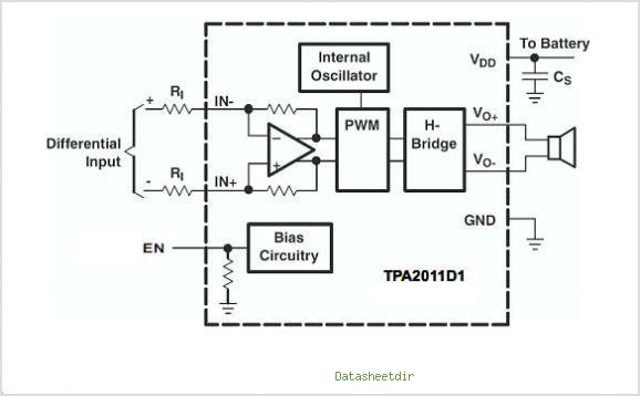
The TPA3007D1 is a 6.5-W mono bridge-tied load (BTL) class-D audio power amplifier featuring high efficiency, which eliminates the need for heat sinks. This amplifier can drive 8-ohm speakers with only a ferrite bead filter required to reduce electromagnetic...
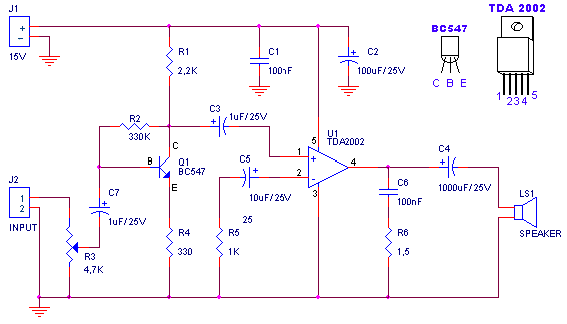
A small amplifier with nice characteristics: Tendency of catering: 15V. Force of expense: 4.2Wrms in the 4W. Minimal signal of entry: 94mVp-p with preamplifier, 0.65Vp-p without the preamplifier. More: Materially: R1=2.2kΩ R2=330kΩ R3=4.7kΩ logarithmic potentiometer R4=330Ω R5=1kΩ R6=1.5Ω C1,...
This is a nice amplifier and very easy to make it. Its an 20W Audio Amplifier based on LM1875 IC. More: Power supply - 48 VDC Output - 20 W, 4 ? Very low distortion (THD - 0.015%), good...
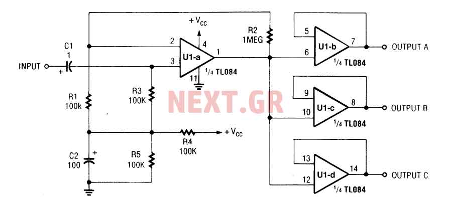
The three-channel amplifier output distribution uses a single TL084. The first step is to capacitive coupling with a 1.0 µF electrolytic capacitor. The entries are railways Vee Y2 or 4.5 V. This allows using a single 9 V power...
High Quality very simple unit - No need for a preamplifier. Can be directly connected to CD players, tuners and tape recorders. Don't exceed 23 + 23V supply. Q3 and Q4 must be mounted on heatsink. D1 must be...
This is a very simple, low cost, Hi-Fi quality power amplifier. You can build it 5 ways, like its shown in the table (from 20 W to 80 W RMS). The first thing that you must do, is to...
Warning: include(partials/cookie-banner.php): Failed to open stream: Permission denied in /var/www/html/nextgr/view-circuit.php on line 713
Warning: include(): Failed opening 'partials/cookie-banner.php' for inclusion (include_path='.:/usr/share/php') in /var/www/html/nextgr/view-circuit.php on line 713