
4 Watt Amplifier with preamplifier
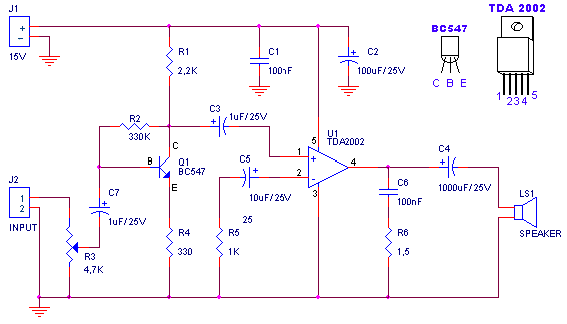
The described amplifier circuit is a compact audio amplification system designed to operate with a supply voltage of 15V, providing a continuous output power of 4.2W into a 4Ω load. The amplifier features a low input signal threshold, requiring only 94mVp-p when used with a preamplifier, or 0.65Vp-p without it, making it suitable for a variety of audio sources.
The circuit components include resistors, capacitors, a transistor, and an integrated circuit (IC) for amplification. The resistors are as follows: R1 (2.2kΩ) acts as a biasing resistor, R2 (330kΩ) helps set the gain of the circuit, R3 (4.7kΩ) is a logarithmic potentiometer that allows for volume control, R4 (330Ω) is used for output loading, R5 (1kΩ) can provide feedback stabilization, and R6 (1.5Ω) is likely a current sensing resistor.
Capacitors play a vital role in this circuit: C1 and C6 (100nF polyester) are used for coupling and decoupling to filter high-frequency noise, while C2 (100μF/25V) serves as a power supply bypass capacitor to smooth voltage fluctuations. C3 and C7 (1mF/25V electrolytic) are used for coupling, and C4 (1000μF/25V electrolytic) provides additional power supply stability. C5 (10μF/25V electrolytic) is another coupling capacitor that can help block DC while allowing AC audio signals to pass.
The transistor Q1 (BC547) is used for signal amplification, while the integrated circuit U1 (TDA2002) is a dedicated audio power amplifier IC that simplifies the design and enhances performance. The output of the amplifier drives a loudspeaker (LS1), which converts the amplified electrical signals back into sound.
The note regarding the loudspeaker's resistance indicates that the output power will vary depending on the speaker's impedance. Lower impedance speakers will draw more current, resulting in higher output power, while higher impedance speakers will reduce the current draw and consequently the output power. This circuit design allows for flexibility in speaker selection, provided the impedance remains within acceptable limits for the TDA2002 IC.A small amplifier with nice characteristics: Tendency of catering: 15V. Force of expense: 4,2Wrms in the 4W. Minimal signal of entry: 94mVp-p with preamplifier, 0,65Vp-p without the preamplifier. Materially: R1=2,2KW R2=330KW R3=4,7KW logarithmic potentiometer R4=330W R5=1KW R6=1,5W C1, C6=100nF polyester C2=100mF/25V ilektrolytjko's C3, C7=1mF/25V electrolytic C4=1000uF/25V electrolytic C5=10uF/25V electrolytic Q1=BC547 U1=TDA2002 LS1=Loudspeaker. Notes: Proportionally the resistance of loudspeaker changes the force that it can give the amplifier
🔗 External reference
Related Circuits
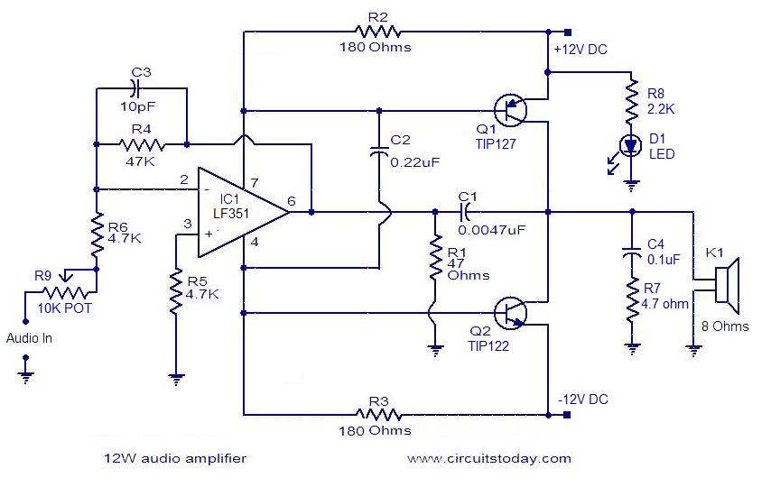
The circuit presented is a simple audio amplifier capable of delivering 12W to an 8 Ohm speaker. The operational amplifier IC TL081 serves as the preamplifier in this design. Alternatively, any operational amplifier with compatible power supply ratings can...
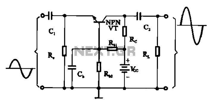
A common base transistor amplifier circuit is characterized by its basic structure, which includes key components such as a biasing resistor, capacitors for coupling, and an amplifying transistor. The circuit features four resistors that establish the quiescent point, with...
This simple, one-transistor amplifier provides a voltage gain of over 1000 (60 dB) for an active aerial impedance crystal earphone. The gain is achieved by replacing the standard load resistor with a constant-current diode that supplies 1/2 mA while...
A common collector amplifier circuit structure and its key components are outlined. The composition of the common collector amplifier circuit is fundamentally similar to that of a common emitter amplifier circuit, with two notable exceptions: one is the collector...
This compact amplifier is built around the TDA2003 integrated circuit, which can deliver 4W RMS at a 4-ohm load. The TDA2003 offers enhanced performance while maintaining the same pin configuration as the TDA2002. It retains the advantageous features of...
If a Squeezebox is present, it is likely accompanied by an amplifier. The inconvenience of manually turning the amplifier on and off, especially when the Squeezebox is stored in a cupboard, necessitates a device that automatically powers the amplifier...