
18W Audio Amplifier
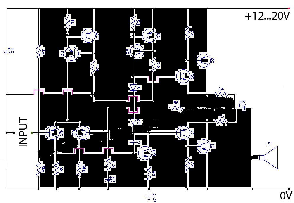
The described unit is a high-quality audio amplifier designed for direct connection to various audio sources, such as CD players, tuners, and tape recorders, without requiring an additional preamplifier stage. This design allows for a simplified integration into audio systems while maintaining audio fidelity.
The power supply requirements specify a dual voltage of 23V, ensuring that the amplifier operates efficiently within its designated power range. Exceeding this voltage could lead to potential damage or reduced performance of the unit.
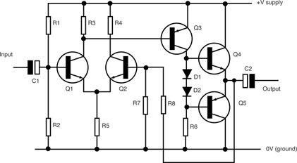
Transistors Q3 and Q4 serve as critical components in the amplifier's output stage. It is essential to mount these transistors on a heatsink to dissipate heat generated during operation, preventing thermal overload and ensuring reliable performance. The placement of diode D1 in thermal contact with transistor Q1 is significant for thermal stability, as it helps regulate the biasing of the output stage, adapting to temperature variations and maintaining consistent performance.
Quiescent current, which is the idle current flowing through the transistors when no input signal is present, is adjustable via resistor R3. The recommended quiescent current range of 20 to 30 mA is crucial for optimal operation, as it affects the amplifier's linearity and distortion characteristics. Measurement of this current should be performed using an Avo-meter in series with the emitter of Q3, ensuring accuracy in the setting process.
For further flexibility in current adjustment, an optional resistor R8 can be added to the circuit. This addition allows for finer tuning of the quiescent current, accommodating variations in component tolerances and user preferences.
Grounding is a critical aspect of the circuit design to prevent hum and ground loops, which can degrade audio quality. A single-point grounding scheme is recommended, where the ground connections of connectors J1, P1, and capacitors C2, C3, and C4 converge. This approach minimizes potential ground loop issues and enhances the overall performance of the audio amplifier. Proper attention to grounding practices will ensure a clean and noise-free audio signal, contributing to the high-quality performance of the unit.High Quality very simple unit -- No need for a preamplifier Can be directly connected to CD players, tuners and tape recorders. Don`t exceed 23 + 23V supply. Q3 and Q4 must be mounted on heatsink. D1 must be in thermal contact with Q1. Quiescent current (best measured with an Avo-meter in series with Q3 Emitter) is not critical. Adjust R3 to read a current between 20 to 30 mA with no input signal. * * * * * * To facilitate current setting add R8 (optional). * A correct grounding is very important to eliminate hum and ground loops. Connect in the same point the ground sides of J1, P1, C2, C3&C4. Co 🔗 External reference
Related Circuits
A DC-coupled single-tube amplifier is a circuit that utilizes a single transistor to amplify DC signals. This configuration primarily consists of a transistor, bias resistors, and minimal coupling capacitors. The absence of coupling capacitors allows the DC operating states...
To configure the amplifier, set resistor R1 to its maximum value and resistor R12 to zero. After this adjustment, power on the amplifier. Adjust R1 until the measured output offset is between 30 mV and 100 mV. Once this...
This is a Class AB transistor power amplifier. It is straightforward to construct, utilizing standard components, and is known for its stability and reliability. The entire circuit employs commonly available parts and can be easily assembled on a general-purpose...
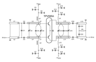
TV RF Power Amplifier 14W. This RF power amplifier operates within the frequency range of 470 - 860 MHz, covering UHF Band IV and V, and delivers an output power of 14 Watts with an input power of 1.5...
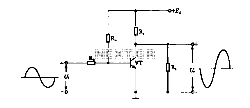
The term amplifier, as used in this article, can refer to either a circuit (or stage) utilizing a single active device or a complete system such as a packaged audio hi-fi amplifier. An electronic amplifier is a device designed...
A peak level indicator is a device that signals when a signal surpasses a specific maximum value. It proves to be particularly beneficial in applications such as tape recorders and mixing consoles. A crucial requirement for a peak level...
Warning: include(partials/cookie-banner.php): Failed to open stream: Permission denied in /var/www/html/nextgr/view-circuit.php on line 713
Warning: include(): Failed opening 'partials/cookie-banner.php' for inclusion (include_path='.:/usr/share/php') in /var/www/html/nextgr/view-circuit.php on line 713