
headphone jacks
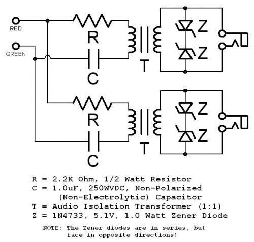
The female connector in question is a standard 3.5mm stereo socket, which typically features three pins: Tip (left channel), Ring (right channel), and Sleeve (ground). This socket interfaces with a corresponding male stereo jack, allowing for the transmission of audio signals from the PC to external devices. In the context of audio coupling between a PC and a telephone line, an audio isolation transformer is employed to prevent ground loops and ensure signal integrity.
The audio isolation transformer, as described, has four terminals on one side and three on the other, indicating that it may consist of two separate coils. The configuration allows for one coil to be connected to the telephone line while the other coil connects to the sound card's output. The impedance measurements taken from the transformer suggest that the side connected to the telephone line has an impedance of approximately 48 ohms, which is suitable for typical telephone line applications. The other side, with an impedance of around 86 ohms, is appropriate for the PC audio output.
To enhance the audio signal transmitted to the telephone line, additional amplification may be required. Implementing an RC-coupled audio amplifier circuit could potentially address the low audio levels experienced. The amplifier should be designed to accommodate the impedance characteristics of the transformer and the telephone line. It is essential to ensure that the amplifier has sufficient gain to elevate the audio signal to an acceptable level for transmission over the telephone network.
In summary, the schematic design should integrate the stereo socket for audio input, the audio isolation transformer for signal coupling, and an appropriate audio amplifier to boost the signal strength before it reaches the telephone line. Careful consideration of component specifications, including transformer ratings and amplifier gain, is crucial for achieving optimal performance in this audio coupling application.actually i wanted to know about the female connector used in PC for connecting the speaker. i hope u got it. i wanted to know the pin connections of the jacks. i shall show u the circuit for the audio coupling of the PC to telephone line. also please suggest me the audio transformer ratings and size, actually im using the eagle layout editor softw are and wanted to know which audio transformer i must connect from the available library. The female connector in the soundcard is a simple stereo socket with 3 terminals for left ch, right ch and ground. The corresponding male stereo jack pin and it`s connections have been posted by TPS. Instead of the RCA jacks you may use mono headphone jacks and corresponding female(mono) sockets as shown in your ckt.
I have got the audio isolation transormer which has got 4 terminals at one end and 3 terminals at the other end. Can anyone tell me connection diagram for this transformer to interface with the telephone line and PC.
The 4 terminals on one side are probably 2 separate coils. If so you may connect your phone line to one coil and the soundcard line-in(or line-out) to 2 terminals on the other side. I measured the impedance of the transformer using the multi- meter and one side i got the impedance around 48 ohms ( which I used for the Telephone side) and on the another between the middle and either one I got the impedance of around 86 ohms ( which is used for the PC side).
and I used the the RC schematics with zener diodes what has been given this forum is working fine. But on the telephone side the audio what Iam getting from PC is very much low. and even i tried with RC Coupled audio amplifier circuit on the telephone side but i didn`t work out. Can anyone tell me how can I amplify this audio signal on the telephone side. I measured the impedance of the transformer using the multi- meter and one side i got the impedance around 48 ohms ( which I used for the Telephone side) and on the another between the middle and either one I got the impedance of around 86 ohms ( which is used for the PC side).
and I used the the RC schematics with zener diodes what has been given this forum is working fine. But on the telephone side the audio what Iam getting from PC is very much low. and even i tried with RC Coupled audio amplifier circuit on the telephone side but i didn`t work out. Can anyone tell me how can I amplify this audio signal on the telephone side. 🔗 External reference
Related Circuits
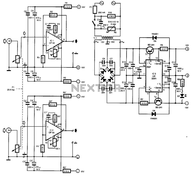
Built around Precision Monolithics Inc. OP-50 operational amplifiers, this amplifier is capable of driving 100- to 14-ohm headphones. It maintains a flat frequency response within 0.4 dB from 10 Hz to 20 kHz and exhibits a total harmonic distortion...
I built this headphone amplifier for dynamic headphones based on my rules of proper audio design. People who know my designs will realize that this amplifier is much more than just a headphone amp. It is a pure class...
Pure Class-A triode OTL design and only one tube for amplification. The plate voltages should be low. The output impedance should be as low as possible and the maximum output current should be as high as possible. This amplifier...
The described shunt-feedback configuration facilitates the straightforward incorporation of frequency-dependent networks, enabling a practical and unobtrusive switchable tilt control as an optional feature. When switch SW1 is in the first position, a gentle shelving bass boost and treble cut...
An operational amplifier designed for medium power applications, utilized as a headphone amplifier capable of driving low loads. The circuit consists of two amplifiers, with a voltage gain set at 40 dB, determined by the resistor pairs R3-R4 and...
An amplifier to drive low to medium impedance headphones built using discrete components. Both halves of the circuit are identical. Both inputs have a DC path to ground via the input 47k control which should be a dual log...