
headphone monitor amp

The Headphone Buffer circuit is a versatile and efficient solution for integrating headphone outputs into various audio equipment. Its compact form factor facilitates installation in tight spaces, making it suitable for modifications to existing devices. The use of the 5532 Dual OpAmp as the core component is pivotal, as it not only minimizes noise but also provides substantial power output, ensuring that headphones receive adequate drive levels for optimal performance.
The operational voltage range of the circuit allows for flexibility in application, accommodating different power supply configurations. This feature is particularly beneficial in environments where unregulated power supplies are prevalent, as the circuit can maintain functionality without the need for precise voltage regulation.
In practical implementation, the circuit can be easily integrated into devices like the FatMan or Theremax, enhancing their usability by allowing for headphone monitoring. The inclusion of a volume control ensures that users can adjust the output level to their preference, which is crucial for maintaining audio quality and preventing damage to headphones from excessive volume levels.
For stereo applications, the recommendation to use a dual-ganged potentiometer allows for synchronized volume adjustment across both channels, providing a balanced listening experience. The instructions accompanying the kit provide clear guidance on this modification, ensuring that users can achieve the desired outcome with ease.
Overall, the Headphone Buffer circuit is an essential addition for any audio equipment lacking a headphone output, enhancing functionality and user experience while maintaining high audio fidelity.This simple amplifier is ideal for adding a headphone jack to equipment that lacks this feature. The Headphone Buffer circuit board is small enough (1. 2" X 1. 4") to squeeze into even the smallest spaces and power requirements are so low that existing supplies in retrofitted gear can be used. It`s a useful addition to many PAiA products such as the Submixer or Submix-Master. Adding a headphone output turns a Stack-In-a-Box it into an incredible practice amp. The key component is the 5532 Dual OpAmp. While ordinarily this part is chosen for it`s low noise characteristics, it is also capable of delivering nearly 350mW of output power per side, more than enough to drive headphones. The circuit can operate from bipolar voltages from +/-5V to +/-18V and it is not absolutely necessary that the + and - supply voltages be the same magnitude.
The superior supply voltage rejection of the IC allows operation with unregulated supplies. In the typical mono application such as adding headphones to a FatMan or Theremax, the Left and Right inputs of the amp are both connected to the Volume control supplied with the kit. For stereo applications a dual ganged pot should be used and this modification is covered in the instructions.
🔗 External reference
Related Circuits
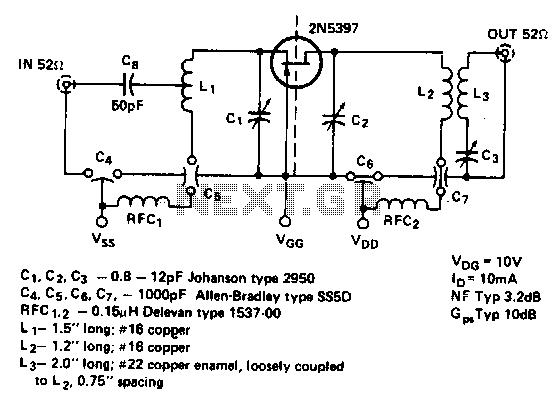
This is a low noise amplifier with a typical noise figure of 3 dB and approximately 10 dB of gain, operating within the frequency range of 450-470 MHz. It is designed for VHF two-way applications. The described low noise amplifier...
The TDA2030 is capable of delivering 20 watts of audio power; however, the output has been intentionally reduced to approximately 8 watts to drive 10-watt speakers, which is sufficient for smaller rooms. The input sensitivity is 200mV, and higher...
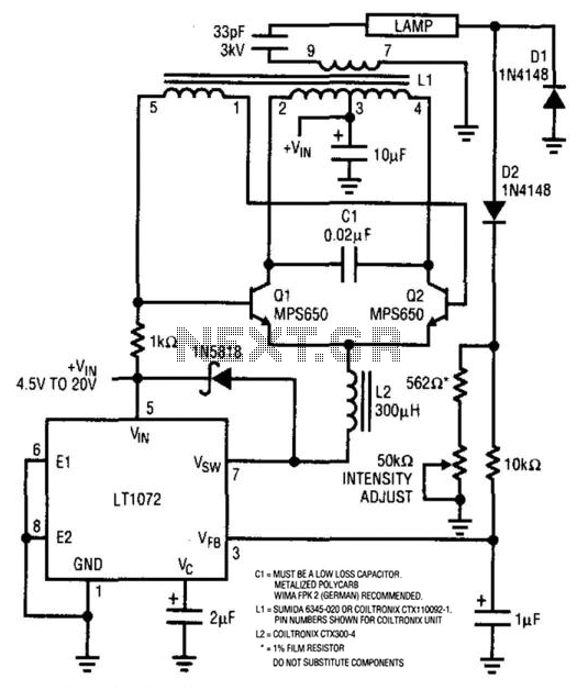
For backlit LCD displays, this supply will drive a lamp. The LT1072 drives Q1 and Q2, while a sine wave appears across C1. L1 is a transformer that steps up this voltage to approximately 1400 V. D1 and D2...
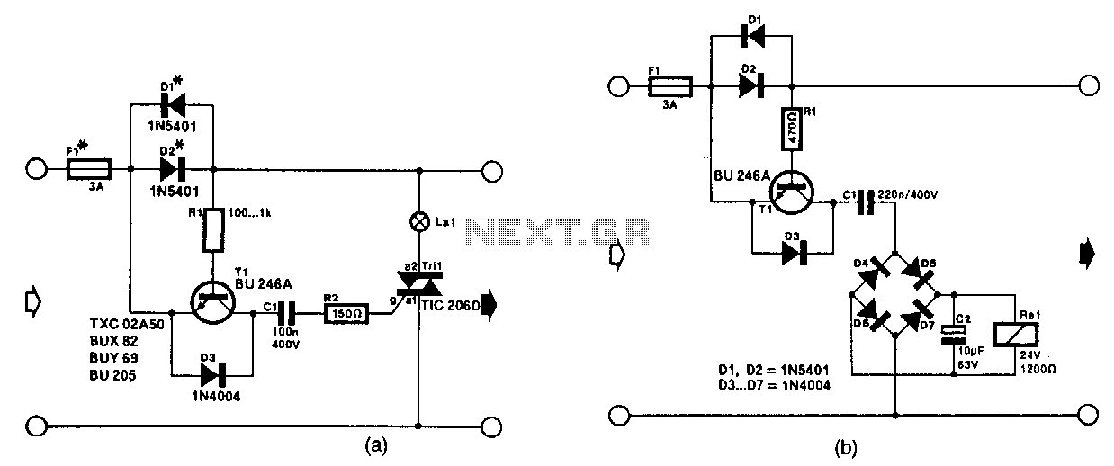
The circuit in Fig. 56-lla activates a signal lamp when it detects a line current consumption exceeding 5 mA and can handle currents of several amperes using suitable diodes in the D1 and D2 positions. Transistor T1 is activated...
This solid-state push-pull single-ended Class A circuit is designed to deliver sound quality comparable to valve amplifiers, providing an output power of 6.9W measured across an 8 Ohm loudspeaker cabinet load. It features reduced total harmonic distortion (THD), increased...
In recent years, following CD's introduction, vinyl recordings are almost disappeared. Nevertheless, a phono preamplifier is still useful for listening to old vinyl discs from a well-preserved collection. This simple but efficient circuit devised for cheap moving-magnet cartridges can be...