
Cold-Cathode Fluorescent-Lamp Supply
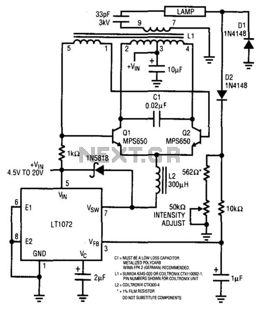
This electronic circuit is designed to drive a backlit LCD display by controlling a high-voltage lamp. The core of the circuit is the LT1072, a precision switching regulator that operates in conjunction with two transistors, Q1 and Q2, to efficiently manage the power supplied to the lamp. The circuit generates a sine wave across capacitor C1, which is crucial for the operation of the lamp.
L1 functions as a transformer, stepping up the voltage to approximately 1400 V, which is necessary for the lamp to achieve optimal brightness. The feedback mechanism is implemented through diodes D1 and D2, which monitor the lamp current. This feedback is fed back to the LT1072 to adjust the output, ensuring consistent brightness and preventing overcurrent conditions that could damage the lamp.
For capacitor C1, a low-loss component is critical to minimize energy loss and improve efficiency. The WIMA FPK 2 is recommended due to its excellent performance characteristics in high-frequency applications.
Inductor L1 can be selected from either the Sumida 6345-020 or Coiltronix CTX110092-1, with specific pin configurations provided for the Coiltronix model to facilitate integration into the circuit. Inductor L2, specified as Coiltronix CTX300-4, plays a role in managing the inductor's performance and ensuring stability in the circuit.
The use of a 1% film resistor in the design contributes to the precision of the feedback loop, allowing for accurate control of the lamp's brightness and enhancing the overall reliability of the circuit. This schematic is suitable for applications requiring efficient backlighting solutions, such as in LCD displays, ensuring both performance and longevity of the components involved. For back-lit LCD displays, this supply will drive a lamp. LT1072 drives Ql and Q2, and a sine wave app ears across CI. LI is a transformer that steps up this voltage to about 1400 V. Dl and D2 detect lamp current and form a feedback loop to the LT1072 to control lamp brightness. C1 = MUST BE A LOW LOSS CAPACITOR. METALIZED POLYCARB WIMA FPK 2 (GERMAN) RECOMMENDED. L1 = SUMIDA 6345-020 OR COILTRONIX CTX110092-1. PIN NUMBERS SHOWN FOR COILTRONIX UNIT. L2 = COILTRONIX CTX300-4 * = 1 % FILM RESISTOR. 🔗 External reference
Related Circuits
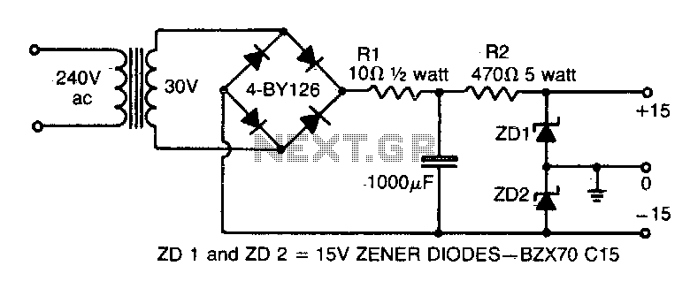
This simple circuit provides both a positive and negative supply from a single transformer winding and a full-wave bridge rectifier. Two zener diodes connected in series create a voltage division, with their junction point grounded. It is important to...
The circuit consists of a series of dual power supplies, providing a symmetrical ±15V supply for linear circuits. The same principle is applicable to non-symmetrical supplies, such as 5.0V and -12V regulators, which are used in applications like registers....
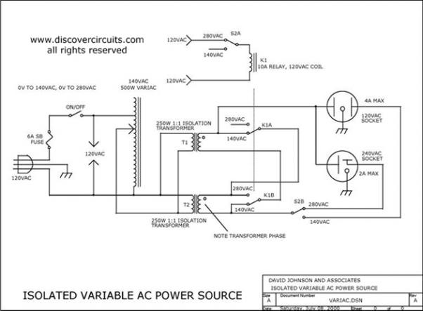
Variable AC Power Supply Circuit. In electronics, it is often useful to have a fully isolated variable AC power supply. With such a device, one can safely test various AC-powered circuits. A variable AC power supply circuit is an essential...
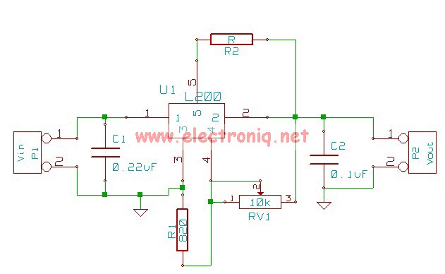
The following circuit illustrates the L200 Regulator Power Supply Circuit Diagram. Features include its use in power supply applications with specified voltage and current. The L200 voltage regulator is a versatile and adjustable linear regulator designed for various power supply...

An electronic rectification circuit that avoids the use of large, heavy, and expensive electrolytic capacitors by utilizing an active transistor in a gyrator configuration. To minimize excess ripple output on a power supply feeding a heavy load, a large...
The circuit diagram for a multiple output digital camera power supply using the MAX1802 is illustrated below. The MAX1802 chip features two buck converters and three boost converters. It accepts an input voltage range of 2.5 to 11V and...
Warning: include(partials/cookie-banner.php): Failed to open stream: Permission denied in /var/www/html/nextgr/view-circuit.php on line 713
Warning: include(): Failed opening 'partials/cookie-banner.php' for inclusion (include_path='.:/usr/share/php') in /var/www/html/nextgr/view-circuit.php on line 713