Heatsink Temperature Monitor Circuit
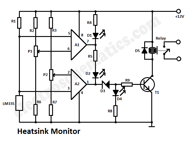
This heatsink temperature monitor circuit uses three LEDs to signal when the temperature exceeds two boundary levels. When the heatsink temperature is below 50 degrees...
This heatsink temperature monitor circuit is designed to provide visual indications of temperature levels using three distinct LEDs. The circuit operates by continuously monitoring the temperature of the heatsink and comparing it against predefined threshold values.
When the temperature is below 50 degrees Celsius, all LEDs remain off, indicating a safe operating condition. As the temperature rises and crosses the first threshold, the first LED lights up, providing an initial warning that the heatsink temperature is approaching a critical level. If the temperature continues to increase and surpasses the second threshold, the second LED activates, signaling an urgent need for attention. The third LED may serve as a final alert or indicate an extreme temperature condition, depending on the specific design of the circuit.
The circuit typically employs a temperature sensor, such as a thermistor or an LM35, which converts temperature changes into corresponding voltage levels. These voltage levels are then processed by a comparator circuit, which compares the sensor output against the set threshold levels. The output of the comparator controls the LEDs, ensuring that they illuminate at the appropriate temperature ranges.
Power supply considerations are essential for the circuit's operation, with a typical voltage range of 5V to 12V being suitable for most applications. Additionally, resistors may be included in series with the LEDs to limit current and prevent damage. A microcontroller can also be integrated into the design for more advanced features, such as data logging or remote monitoring capabilities.
In summary, this heatsink temperature monitor circuit serves as a vital tool for ensuring the safe operation of electronic components by providing clear visual feedback on temperature levels, allowing for proactive measures to be taken before overheating occurs.This heatsink temperature monitor circuit signals via 3 LEDs when the temperature exceeds 2 boundary levels. When the heatsink temperature is below 50.. 🔗 External reference
