
Automobile AM radio circuit
The circuit is designed to facilitate the reception of medium wave radio frequencies, which are essential for AM broadcasting. The use of a tunable diode, such as the BB113, allows for precise frequency adjustment, enabling the user to select different radio stations within the specified frequency bands. The loop tuning method enhances selectivity and sensitivity, which is critical for clear audio reception in automotive environments where interference can be prevalent.
The main coils are integral to the circuit's performance. The coils L1 and L2, both with 122 turns, serve as the primary inductors for tuning and signal amplification. L3, with 68 turns, may act as a secondary inductor to improve the overall gain of the circuit. Coupling coils L5 and L6, with 96 and 64 turns respectively, are designed to transfer energy between different stages of the circuit while maintaining impedance matching, which is crucial for minimizing signal loss.
The wire specifications, using 8 × 0.03 mm copper, indicate a focus on minimizing resistive losses within the coils, which is essential for maintaining signal integrity. The additional coil L7, with 90 turns, may be used for further tuning or as part of a feedback loop to stabilize the circuit's operation.
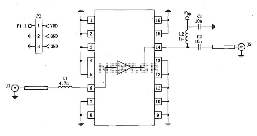
Overall, this car radio circuit exemplifies a well-thought-out design that balances performance and efficiency, making it suitable for automotive applications where reliable radio reception is necessary.This circuit shows the high and mid part of car radio, and the medium wave band I is 520 ~ 950kHz, Poland II is 900 ~ 1640kHz. Loop tuning uses tunable diode BB113.Main coil data:L1: 122 turns; L2: 122 turns ; L3: 68 turns ; L5: 96 turns ( coupling coil with 7 turns ); L6: 64 turns ( coupling coil with 5 turns).
L1 ~ L6 use 8 × 0.03 copper.L7: 90 turns, 6.. 🔗 External reference
Related Circuits
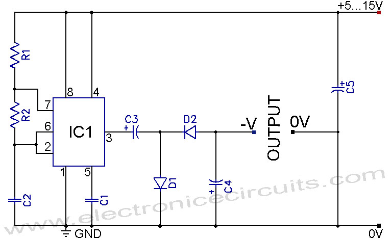
A 555 negative voltage power supply circuit can be created using a charge-pump configuration that incorporates a 555 timer, diodes, and additional components. The 555 timer is a versatile integrated circuit commonly used in various applications, including oscillators, timers, and...
VCR Camera Video Detector Switch Controller Circuit. This video detector switch controller circuit utilizes the video output from a VCR or camera to... This circuit functions as a video detector switch controller, designed to manage the video output from a...
A 50-ohm impedance is illustrated in the RF2320 linear amplifier circuit, which is configured for input and output using transmission lines and inductive or capacitive components to create a matching network. The RF2320 linear amplifier circuit is designed to operate...
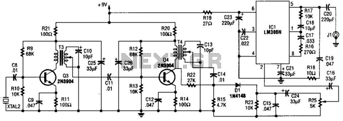
The 2.25-MHz oscillator Q1 drives amplifier Q2 and XTAL1, an ultrasonic transducer. The transducer is a lead zirconate-titanate type. Taps on T1 and T2 provide low-impedance drive points. The circuit consists of a 2.25-MHz oscillator (Q1) that serves as the...
This is a pressure sensor signal conditioning circuit. It is a simple and inexpensive circuit due to its small geometry and the use of a straightforward pressure sensor. The pressure sensor signal conditioning circuit is designed to convert the raw...
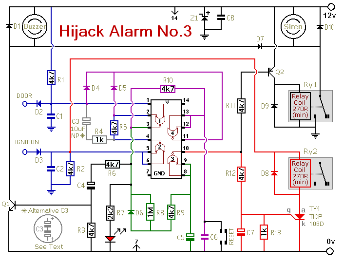
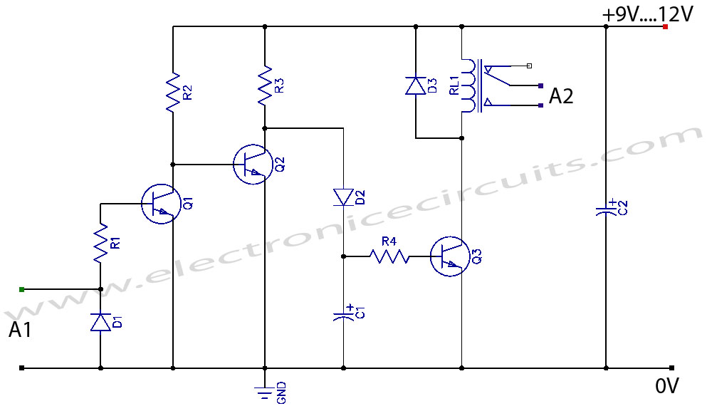
Similar to the initial two Hijack Alarms, this circuit is designed to activate if a door is opened while the ignition is switched on. After a delay of several minutes, allowing the thief to move a safe distance away,...
Warning: include(partials/cookie-banner.php): Failed to open stream: Permission denied in /var/www/html/nextgr/view-circuit.php on line 713
Warning: include(): Failed opening 'partials/cookie-banner.php' for inclusion (include_path='.:/usr/share/php') in /var/www/html/nextgr/view-circuit.php on line 713