
Infra/radio remote control encoder/decoder with PIC

This remote control project leverages programmable PIC microcontrollers to create a versatile system capable of operating through infrared and radio frequency signals. The choice of using either fixed encoder/decoder ICs or programmable microcontrollers allows for flexibility depending on the user's familiarity with programming. The integration of well-established ICs such as the Holtek HT-12 series and Motorola models ensures reliability and ease of implementation.
The project employs a straightforward architecture where the transmitter captures the state of multiple buttons, encoding these states into a digital signal that is transmitted to the receiver. The design ensures that only one button can be pressed at a time, simplifying the decoding process and enhancing operational efficiency. The encoding mechanism translates the state of each button into a binary message, allowing for asynchronous changes in input states, which is crucial for responsive remote control applications.
The system's versatility is further enhanced by the ability to configure the transmitter and receiver addresses, ensuring compatibility between devices. The transmitter's capability to send latched and toggle outputs provides additional functionality, catering to various control scenarios. The receiver's design incorporates relay-switched outputs, allowing for both momentary and latched operations, which can be tailored to specific application requirements.
The inclusion of an LCD display for monitoring received packets and communication errors adds a layer of user feedback, facilitating troubleshooting and enhancing the overall user experience. The project is suitable for a wide range of applications, from simple remote controls to more complex automation systems, providing a robust solution for wireless communication needs.This is a general purpose remote control project with using programmable PIC microcontrollers. Schematics are shown for using infrared (RF) or radio (RF) media. If you are not familiar with microcontroller programming, you can use fixed encoder and decoder integrated circuits instead. Well-known such IC-s are Holtek HT-12D, HT-12E and Motorola MC1 45026, MC145027, MC145028. Remote controls usually consist of encoder/decoder parts connected to a transmitter/receiver module which takes care of the transmission of digital signals by radio or infra waves. The format of this project`s signal is designed to be ideal even for the cheapest ASK RF modules (using 50% signal/silence ratio), and it is similar to the Philips RC-5 format used in infrared remote controls.
The transmitter has a varying number of buttons and sends the states of these inputs to the receiver. The receiver device decodes the message and sets the outputs accordingly. You can press at most one key at a time on the encoder, and only the code for the pressed key is sent to the decoder.
This is an efficient method for general remote control The input to the encoder is the state of buttons or TTL inputs. Every input channel state is encoded into each message sent to the decoder (one bit per channel), so TTL inputs can change asynchronously, and any number and combination of buttons can be pressed and encoded, the same state is reproduced on the decoder outputs.
This method is suitable for modeling AND remote control, but messages are longer. Analog channels would also be possible, but are not yet implemented Current devices have 4 or 8 channels - it means they are capable of controlling the state of 4 or 8 switched outputs. Each transmitter and receiver has an address, and the transmitter address must match the address of the receiver to control the channels.
The transmitters are capable of sending three different types of codes for the available channels: latched output - the last received state is kept. The channel output can be toggled on/off by a momentary button press, or the output can be turned on or off by specific ON/OFF-type transmitter codes Combining different code-type transmitters with receivers with different type channels, great versatility is achieved.
The possible combinations are described below. The transmitter has 8 buttons. The 8-channel transmitter can be used for controlling 8 channels by sending simple codes, the 4-channel transmitter can be used with four ON and four OFF buttons for 4 channels. The diode wires (J1-J4) determine the transmitter address. The number of channels (and button functions) depends on the PIC code used. The transmitter has 8 buttons. The 8-channel transmitter can be used for controlling 8 channels by sending simple codes, the 4-channel transmitter can be used with four ON and four OFF buttons for 4 channels.
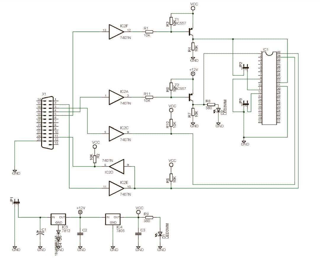
The diode wires (J1-J4) determine the transmitter address. The number of channels (and button functions) depends on the PIC code used. The receiver has 8 relay-switched NO/NC outputs for 8 channels. Each channel can be set to momentary or latched operation. The address is set by switch S1. The schematic shows the RF version of the receiver, the IR version differs only in the receiver module - a 3-pin IR receiver IC, like TSOP1738 is used The receiver has 4 or 8 relay-switched NO/NC outputs for 4 channels. Each channel has both momentary AND latched outputs (2 outputs per channel). LM[0-3] outputs are latched outputs of channels, and LM[4-7] outputs are momentary outputs of channels.
The 4-relay PCB can be re-wired to select momentary or latched output for the four relays. The address is set by switch S1. The schematic shows the RF version of the receiver, the IR version differs only in the receiver module - a 3-pin IR receiver IC, like TSOP1738 is used The receiver is to display received packets and communication errors on a 2x16 character LCD display. T 🔗 External reference
Related Circuits
This is a variable power supply controlled by a PIC microcontroller. An LCD display is included in the circuit to show the actual output voltage and current values. A push-button switch is used to adjust the output voltage and...
High-end audio equipment is typically controlled digitally by a microprocessor (microcontroller) system. It is necessary to have a digital interface that allows for effective communication and control. High-end audio systems utilize a microcontroller to manage various functionalities, enabling precise control...
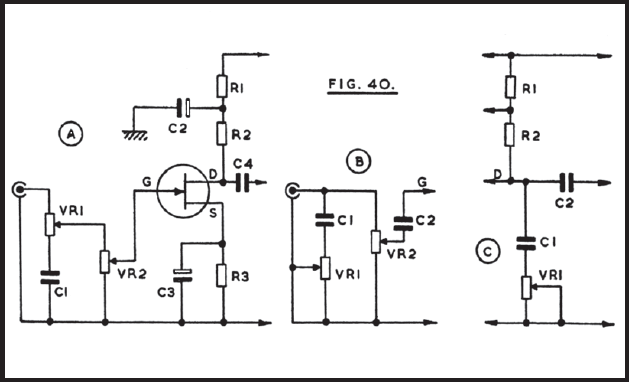
The circuit operates from a 12V or similar power supply, with the option to adjust resistor R1 for higher voltage applications. There is significant flexibility in selecting values for components like capacitor C1. At point B, VR1 serves as...
This circuit allows for amplifier volume control without the need for a potentiometer, utilizing an IC DS1669. The operating voltage for this type of IC ranges from 4.5 volts to 8 volts; however, in this circuit, it is used...
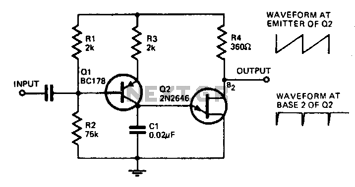
With the component values shown, the oscillator has a frequency of 8 kHz. When an input signal is applied to the base of Q1, the current flowing through Q1 is varied, thus affecting the time required to charge C1....
The SCHAER+ programmer is a programmer for PIC18 family from a PC parallel port (LPT). It is derived from the SCHAER programmer I used to download my projects in PIC1684. The SCHAER+ programmer should be improved to use a...