
Hexfet Switch Circuit
The hexFET (High Electron Mobility Field Effect Transistor) is a type of power transistor that is particularly effective for switching applications in DC circuits. Its ability to handle high voltages and currents makes it suitable for controlling a wide range of devices such as relays, motors, and lamps.
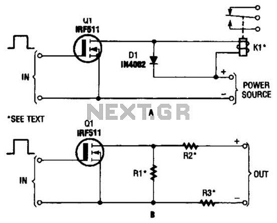
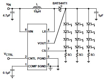
In the described circuit, the hexFET is employed to control the flow of DC power to multiple outputs. The configuration allows for the dynamic switching of resistive loads, represented by R1, R2, and R3, which can be incorporated into or excluded from the circuit as needed. This feature enhances the flexibility of the circuit design, enabling it to adapt to various operational requirements.
The switching action is typically controlled by a gate voltage applied to the hexFET, which allows for rapid transitions between the on and off states. When the gate voltage exceeds a certain threshold, the hexFET enters the conduction state, allowing current to flow through the load. Conversely, when the gate voltage is removed or reduced below the threshold, the hexFET turns off, interrupting the current flow.
This capability is particularly advantageous in applications where load management is crucial, such as in automated systems where different devices need to be activated or deactivated based on specific conditions. The use of resistive loads in the circuit allows for testing and calibration of the switching mechanism, ensuring reliable operation under varying conditions.
Overall, the integration of hexFETs in DC power switching circuits provides an efficient and reliable solution for controlling multiple devices, contributing to the overall performance and functionality of electronic systems. The hexFET can swatch dc power to relays (as shown in A), motors, lamps, and numerous other-devices. That arrangement can even be used to switch resistors in and out of a circuit, as shown in B. Rl, R2, and R3 represent resistive loads that can be switched in and out of the circuit. 🔗 External reference
Related Circuits
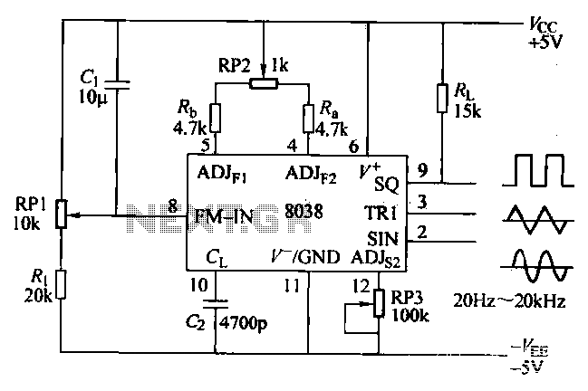
The ICL8038 function generator is an audio composition device that utilizes the ICL8038 integrated circuit. The resistance Ri potentiometer RP1 is used to determine the flow potential. Typically, the output is set to approximately 2Vcc / 3. Lowering the...
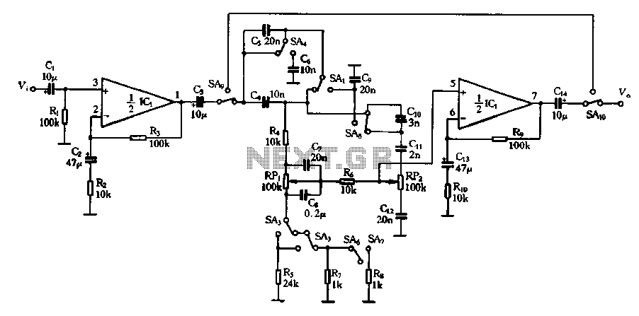
Figure 4-13 illustrates a modified version of a standard attenuated tone control from the pitch selector. It features two amplification stages of amplifiers 10 and Icl utilized as line amplifiers. Capacitor C2 is employed to compensate for tone attenuation...
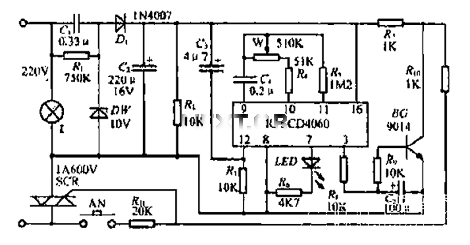
The circuit includes a CD4 component with a connection of 16 feet for the Vcc terminal, 8 feet for the ground, 12 feet for the reset terminal, 7 feet for the Qt end, and 3 feet for the Q...
This circuit provides a simple visual indication of audio level signals, adaptable to various user requirements. It can be configured for different input levels, which can be adjusted using trimmer potentiometers TR1 (state) and TR2 (gain). The audio signals...
The all-analog circuit presented controls the rate at which a miniature turbojet engine can be throttled. Increasing or decreasing the throttle too quickly on a miniature turbojet engine, or any jet engine, can lead to quick failure in flight,...
A simple white LED driver schematic can be created using the EL7513 constant current boost regulator, which is specifically designed for driving white LEDs. This driver can manage 4 LEDs in series or up to 12 LEDs in a...