
EL7513 led driver circuit design
The EL7513 constant current boost regulator is a highly efficient solution for driving white LEDs, making it suitable for various applications, including backlighting and decorative lighting. The architecture of the circuit allows for flexibility in LED configurations, enabling designers to choose between series and parallel arrangements based on their specific requirements.
In a typical application, the EL7513 operates by boosting the input voltage to a level sufficient to drive the desired number of LEDs. The device regulates the output current to ensure that each LED receives a consistent current, which is crucial for maintaining uniform brightness and prolonging the lifespan of the LEDs. The use of a PWM signal for dimming control allows for efficient brightness adjustment without significant power loss, making it ideal for applications where energy efficiency is paramount.
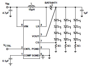
The capacitor (C3) connected to the frequency control pin influences the switching frequency of the regulator. A value of 4700pF is recommended for operation below 200Hz, which is suitable for applications where flicker-free illumination is desired. The RC filter before the CNTL pin smooths the PWM signal, ensuring that the regulator responds appropriately to changes in the control signal and maintains stable output current.
The shutdown feature of the EL7513 is particularly beneficial for battery-operated devices, as it minimizes power consumption when the device is not in use. By ensuring that the supply current drops below 1µA when in shutdown mode, it contributes to overall energy savings and extends battery life.
Overall, the EL7513 LED driver circuit is an effective and efficient solution for applications requiring reliable and adjustable LED illumination, with a straightforward design that can be easily integrated into various electronic projects.A very simple white led driver schematic circuit can be designed using the EL7513 constant current boost regulator specially designed for driving white LEDs. It can drive 4 LEDs in series or up to 12 LEDs in parallel or series configuration and achieves efficiency up to 91%.
with frequency less than 200Hz (for C3 = 4700pF). When a higher frequency PWM is used, an RC filter is recommended before the CNTL pin. When the level falls below 0. 1V, the chip goes into shut-down mode and consumes less than 1 A of supply current for VIN less than 5. 5V. As you can see this circuit diagram led driver is designed for maximum efficiency, and drives 3 legs of 4 LEDs in a series configuration.
The input voltage required for this led driver application circuit must be around 2. 7 and 4. 2 volt, typically 3. 3 volt. 🔗 External reference
Related Circuits
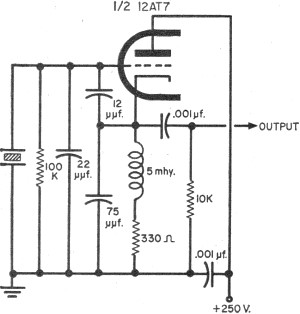
To update the fundamental oscillator circuits, simply replace the transistors with tubes. Alternatively, if one owns a vintage vacuum tube radio, it may be of interest to learn about historical practices. In general, the foundational principles of electronic circuits...
The circuit employs 60 individual LEDs to represent the minutes of a clock and 12 LEDs to indicate the hours. The power supply and time base circuitry are consistent with those described in the previous 28 LED clock circuit....
The circuit described can connect two telephones in parallel and function as a two-line intercom. Typically, a single telephone is connected to a telephone line. When another telephone is needed at a distance, a parallel line is utilized for...
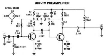
This is a low-cost, antenna-mounted UHF TV pre-amplifier circuit that can provide more than 25 dB of gain. The first stage of the pre-amplifier is biased for optimum gain. L1 and L2 are strip line equivalents with a length...
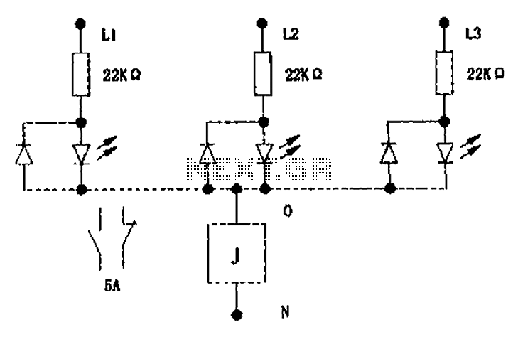
The circuit illustrated below activates a small relay (J) when there is an imbalance in any one phase of a three-phase circuit. This relay triggers an external control contact, which immediately disconnects the power supply to the main circuit...
This slideshow is based on the LED Design Ideas Collection, which features a compilation of LED-related circuits and design applications submitted by readers and published in EDN's Design Ideas section. Users can browse through the circuit schematics in this...