
HF transceiver
The design of the described transceiver encompasses various critical elements that contribute to its performance and functionality. The selection of intermediate frequencies is a pivotal aspect, as it directly impacts the receiver's ability to filter out unwanted signals while maintaining the integrity of the desired signal. The use of electromechanical and quartz crystal filters allows for precise tuning and selectivity, essential in communication applications where clarity and reliability are paramount.
In the implementation of the variable first IF and fixed second IF configuration, the transceiver benefits from a simplified architecture that minimizes the need for complex switching mechanisms, thus enhancing operational reliability. The choice of MOSFETs in amplification stages is particularly advantageous due to their inherent characteristics, which allow for efficient signal processing and control. The integration of automatic gain control further optimizes the transceiver's performance in varying signal conditions, ensuring consistent output levels.
The band-pass filters and mixers are designed with careful consideration of the frequency response and signal integrity. The use of JFETs in the mixers provides low noise performance, which is crucial for maintaining signal quality during both reception and transmission. The design also emphasizes the importance of minimizing interference between channels, which is achieved through the careful selection of resonant circuits and the implementation of effective filtering techniques.
Overall, the described transceiver exemplifies a well-thought-out design that balances complexity with functionality, making it suitable for both amateur and professional communication applications. The attention to detail in the choice of components and the configuration of the circuit ensures that it meets the demanding requirements of modern communication systems.The choice of IF is usually determined from availability of filters with desired characteristics. For communication receiver or transceiver the requirements for main selective element are very high, and usually two types of filters are used: electromechanical (f~200-500kHz) and quartz crystal (f~5-9 MHz). But if low IF is used, the relative difference in frequency between fundamental and mirror channels becomes to small for input signals with F>4-5 MHz, and necessary suppression of mirror channel becomes unachievable by using common resonant LC-band-filters. two fixed intermediate frequencies, the first one in range about 3-8 MHz, and the second one - about 465-500 kHz.
In this case, main signal filtering occurs on the second IF. variable first IF and fixed second IF. This is very common variant for homebrewed transceiver, because it has following very important advantage: variable frequency oscillator (VFO) works on rather low frequencies and is not switched by bandswitch. However, in this case all bands have the same width, which doesn`t correspond with amateur radio frequencies first IF higher, then highest received frequency, for example 35 MHz.
This principle is used in many modern communication receivers. The advantage is, that no band-pass filters (BPF) are required for each band, because mirror frequencies are outside HF and can be suppressed by appropriate non-switchable low-pass filter at the input. But it requires high-frequency VFO (usually digital frequency synthesizer), which is difficult to make at home My SSB/CW transceiver, that i describe below, has 2 fixed intermediate frequencies, the first one is 5.
5 MHz, and the second (main) one is 500 kHz. This choice is not mine, i just followed the described UA1FA transceiver schematics. The main selective element is electromechanical filter with passing frequency range 500. 3-503 KHz (bandwidth=2. 7 KHz), which perfectly fits for an SSB operation. For the CW operation the frequency range is additionally narrowed in the audio amplifier. CW-lovers may wish to add separate IF filter for this mode, though it seems to me unreasonable, at least for the beginner. Most of amplification stages both in RX and TX channels use MOSFETs, because they have low noise, flat frequency response and ability to change gain remotely by changing the voltage on the second gate.
The latter is used in AGC (automatic gain control) circuit and also in RX/TX switching to close unused channel. The only disadvantage of MOSFETs is rather high price (at least, in Russia) and ease to damage by static electricity.
Band-pass-filters for each band, they are switched by bandswitch by small-sized electromagnetic relays. Each filter consist on two resonant LC-circuits with connecting capacitors, which are chosen to provide flat frequency response within the band (there is no tuning of BPF occurring simultaneously with VFO tuning).
Mixers with first IF filter. There are 4 mixers (two in RX, two - in TX). All of them are identical and are made using JFETs. First IF filter has 3 identical resonant circuits with inductive connection. It is enough to suppress mirror-channel signals for 2-nd mixer. Variable frequency oscillator (VFO) with internal buffer amplifier. The frequency of VFO is changed by variable capacitor and switched by bandswitch by electromagnetic relays. External (second) buffer amplifier for VFO. It appeared to be required, because without it the influence of transceiver`s circuit over VFO was too high, causing frequency deviation while transmitting and unavoidable `jumps
🔗 External reference
Related Circuits

The relay power in the linear circuit is derived from a -120 V bias supply, while the transmit keying output from the Kenwood device is +12 V with a maximum current of 10 mA. A critical component of this...
1. Full 5 watt output using a power MOSFET final that is resistant to high SWR and thermal runaway. This final is very efficient and runs much cooler than traditional bipolar designs. 2. Highly sensitive and selective superhetrodyne receiver...
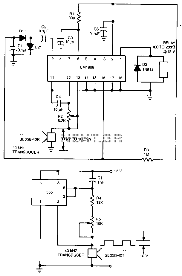
This ultrasonic transmit/receive circuit operates at 40 kHz. Control resistor R5 adjusts the frequency for optimal performance with the transducers used. The ultrasonic transmit/receive circuit designed to operate at a frequency of 40 kHz is essential for applications in distance...
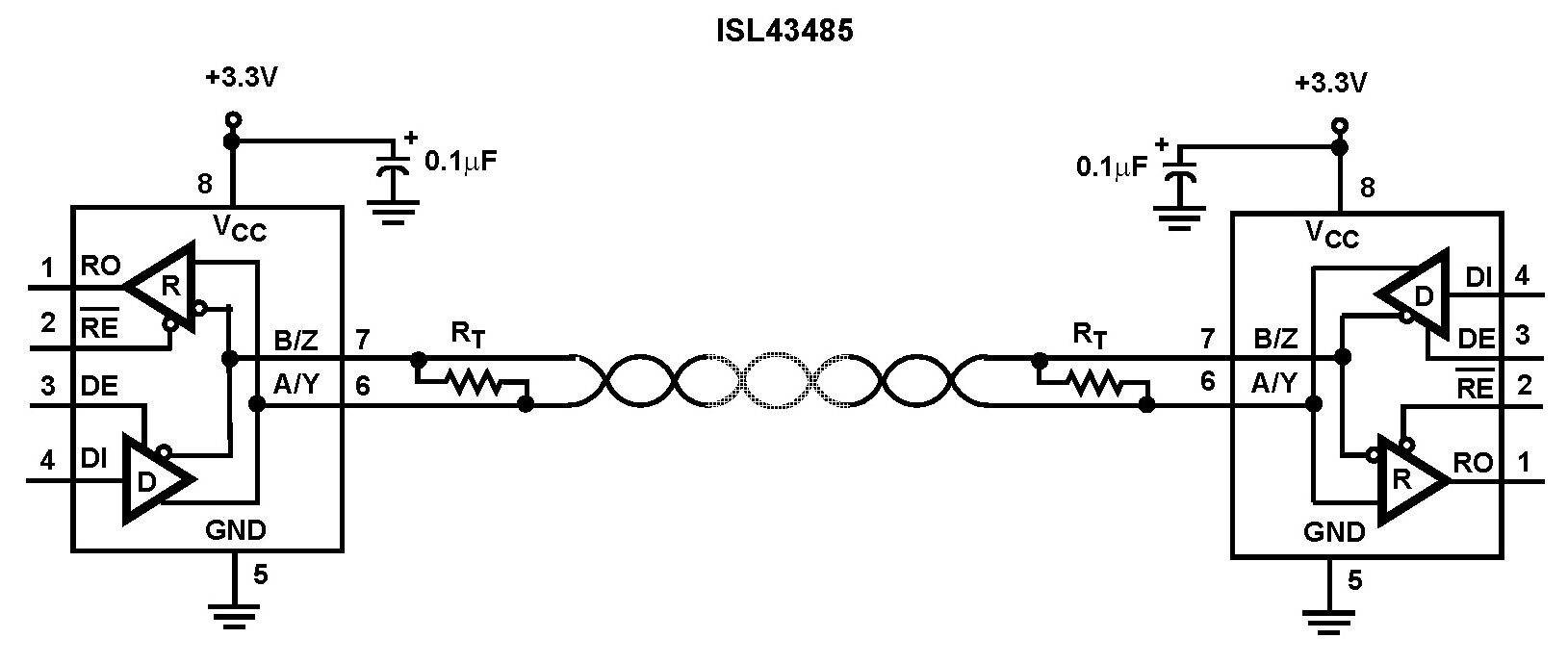
The Intersil ISL43485 is a high-speed BiCMOS transceiver powered by 3.3V, designed to comply with both RS-485 and RS-422 standards for balanced communication. This transceiver is specified for power supply tolerances of 10%, ranging from 3V to 3.6V. The...
Several RS232 transceiver circuits are used for communication between microcontrollers and other devices, such as PCs or RS232 devices. This document presents a collection of well-known RS232 transceiver circuits. The circuit utilizes the MAX232 from Maxim's devices, which is...
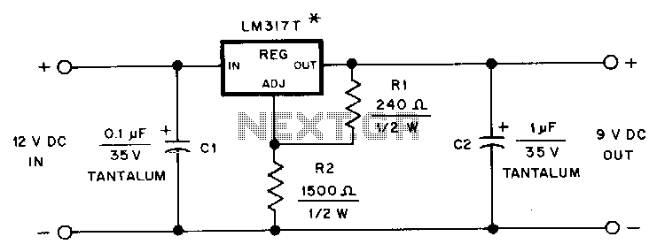
This adapter provides a regulated 9-V source for operating a Kenwood TR-2500 hand-held transceiver in a vehicle. The mounting tab of the LM317T is electrically connected to its output pin, which should be considered during the construction of the...