
Relay Interface For Amateur Radio Transceivers Circuit

The described circuit features a relay that operates from a negative bias voltage of -120 V, which is essential for the linear amplifier's functionality. The relay is activated by a transmit keying signal sourced from a Kenwood device, delivering a +12 V signal with a maximum current capability of 10 mA. This configuration allows for efficient control of the relay, enabling it to switch the high-voltage line as required for transmission.
The PNP driver transistor plays a pivotal role in this setup. It is selected for its ability to manage high voltage levels, specifically rated for a minimum of 150 V, which ensures it can safely switch the relay without risk of breakdown. Additionally, the transistor is designed to handle a current of around 250 mA, providing sufficient drive capability to energize the relay coil effectively.
In practical applications, the circuit would typically include biasing resistors to set the operating point of the PNP transistor, ensuring it remains in the active region during operation. Protection components, such as diodes, may also be included to prevent back EMF generated by the relay coil from damaging the transistor when the relay is de-energized.
Overall, this circuit exemplifies a robust design for controlling high-voltage relay operations using a low-voltage control signal, ensuring reliable performance in linear amplifier applications. The relay power in the linear is obtained from the -120-V bias supply, and the transmit keying output from the Kenwood is +12 V at 10 mA maximum. The key ingredient in the circuit is the pnp driver transistor, which must be capable of handling at least 150 V at about 250 mA. 🔗 External reference
Related Circuits

The circuit designed for distortion measurements eliminates the fundamental frequency of 1 kHz, enabling the assessment of the residual harmonic levels. Initially, a true RMS meter is employed to measure the 1-kHz input level (E^) by positioning the switch...
This high voltage converter circuit begins with a 30-volt power supply and is capable of delivering output voltages ranging from 0 to 3 kV for version 1, or from 0 to 10 kV for version 2. The high voltage converter...
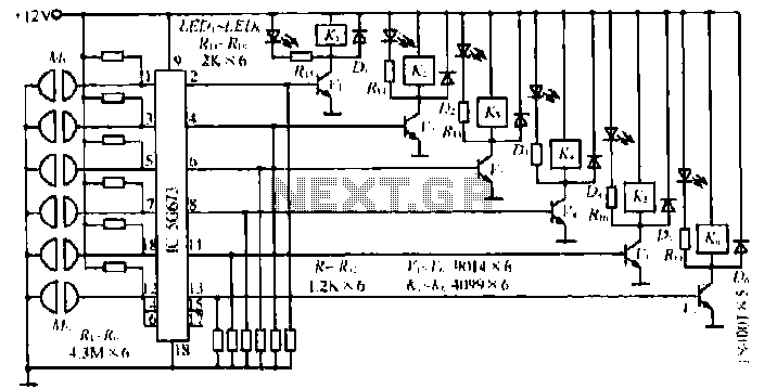
A, B, and C are used for a high-power split-phase system. The A + B' C' arrangement serves as a phase line for a range generator. The A-A' indole path string includes two 220V / 15W bulbs, which are...
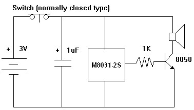
The M8031 circuit features an integrated RC oscillator and digital envelope circuits, which minimize the need for external components. It produces a sound that mimics a mechanical ding-dong. The M8031 operates with a low input voltage range of 1.3...
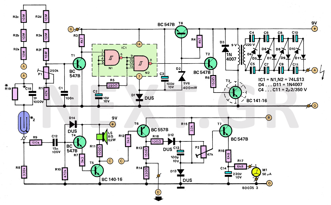
This page demonstrates how to construct a Geiger-Müller counter, an essential device that not only indicates the presence of radioactive materials but also highlights the associated dangers. The Geiger-Müller counter operates similarly to a photometer, measuring high-energy particle radiation...
This circuit employs an astable multivibrator to alter the state of a signal based on specific conditions. It also incorporates a flip-flop, which retains the state of the output once a change is detected, completing a cycle of the...
Warning: include(partials/cookie-banner.php): Failed to open stream: Permission denied in /var/www/html/nextgr/view-circuit.php on line 713
Warning: include(): Failed opening 'partials/cookie-banner.php' for inclusion (include_path='.:/usr/share/php') in /var/www/html/nextgr/view-circuit.php on line 713