
Hi-Low Logic Digital tester
The circuit operates by utilizing a 7-segment LED display configured as a common cathode, which allows each segment to be illuminated by applying a high signal to the appropriate segment pin. The logic level tester interprets digital input signals and displays corresponding values on the 7-segment display. When the input signal is high (logic level '1'), the display shows an 'H'. Conversely, when the input signal is low (logic level '0'), the display shows an 'L'. In cases where the input is not connected, the display indicates 'N' for open.
The core of the circuit relies on a TTL NAND gate integrated circuit (74LS00), which contains four 2-input NAND gates. These gates are used to process the input signal and determine which segments of the display should be activated. The transistors in the circuit serve as switches, allowing the control signals from the NAND gates to drive the segments of the display without exceeding the current ratings of the logic gates.
Resistors R1, R2, R5, and R6, each with a value of 10 kOhm, are used for biasing and current limiting, ensuring that the transistors operate within safe limits. Resistor R3, valued at 47 kOhm, may be used for pull-down purposes or to set the base current for one of the transistors. Resistor R4, at 8.2 kOhm, is likely utilized to limit the current to one of the segments of the display. Resistors R7, at 4.7 kOhm, and R8-R12, each at 330 Ohm, are employed to control the current through the segments of the display, ensuring they illuminate correctly without damage.
In summary, this circuit effectively demonstrates the logic levels of digital signals using a 7-segment display, powered by a TTL NAND IC and controlled by transistors, with carefully selected resistor values to manage current and voltage levels throughout the system.This tester, the logic level digital signals indicate on a 7-segment display. The display shows an H as the input signal is high. When the signal is low, the display shows an L on. If the input is open, the display shows N. The circuit consists of a TTL NAND IC type 74LS00 and three transistors. The NAND gates ensure that the right segments of the display can be controlled. The display is of the type CC (common cathode ie common cathode). R1, R2 = 10 kOhm R3 = 47 kOhm R4 = 8.2 kOhm R5, R6 = 10 kOhm R7 = 4.7 kOhm R8-R12 = 330 ? LD1 = 7 segment LED display (common cathode) IC1 = IC TTL 74LS00 🔗 External reference
Related Circuits
This device is designed to maintain a deep cycle battery using energy harvested from a solar panel. It functions as a combination of a digital clock timer and a solar panel charge controller. Component: .. This circuit serves the dual...
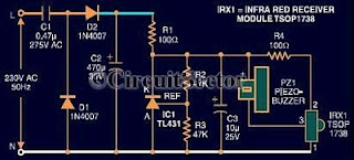
An infrared remote control tester circuit that can be constructed inexpensively. This IR tester is built around an infrared receiver module TSOP1738. The remote control's state can be observed through the sound of a buzzer. The circuit is highly...
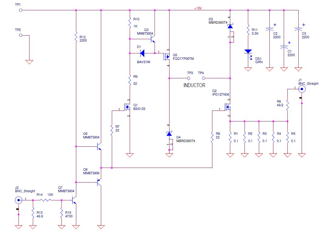
Yes, it does charge the inductor again. Diodes are beneficial as they do not charge the inductor back but dissipate a significant amount of instantaneous power due to the forward voltage drop. One approach would be to monitor the...

This compact circuit is designed to verify the basic functionality of an infrared remote control unit. It operates on the straightforward principle of connecting a piezo buzzer directly to an infrared (IR) receiver integrated circuit (IC). This approach is...
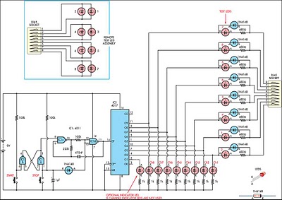
This circuit was developed to create a simple network tester that can be operated by a single individual. Commercial units typically require a second person to monitor the remote LEDs, as the transmitters lack the ability to continuously cycle...
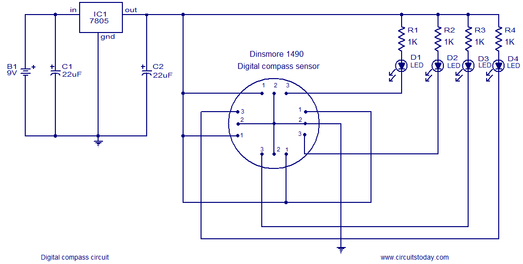
The following circuit illustrates a Digital Compass Circuit. This circuit is based on the 7805 IC. Features include a simple and accurate electronic compass. The Digital Compass Circuit utilizes the 7805 voltage regulator to provide a stable 5V supply necessary...
Warning: include(partials/cookie-banner.php): Failed to open stream: Permission denied in /var/www/html/nextgr/view-circuit.php on line 713
Warning: include(): Failed opening 'partials/cookie-banner.php' for inclusion (include_path='.:/usr/share/php') in /var/www/html/nextgr/view-circuit.php on line 713