
Simple Cat.5 Network Tester
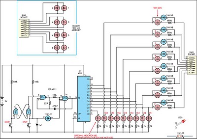
This network testing circuit employs a 4011 quad 2-input NAND gate to facilitate its operations. The RS flip-flop configuration (IC1a and IC1b) allows for the storage of a binary state, which is essential for controlling the clock oscillator (IC1c and IC1d). The oscillator generates a square wave signal, which is critical for sequentially activating the 4017 decade counter. The 4017 counter is responsible for sequentially lighting one of the eight LEDs corresponding to the RJ45 socket connections.
The Start switch initiates the operation, allowing the oscillator to run continuously, while the Stop switch pauses the operation, providing a manual stepping feature through the lines. The presence of diode D1 enables the manual clocking feature, which is useful for troubleshooting and verifying individual connections without continuous cycling.
The circuit is designed with user-friendliness in mind, allowing one person to perform network tests efficiently. When a test LED lights up, it confirms the integrity of the cable connection; conversely, when the LED does not illuminate, it indicates an open circuit. The ability to detect shorts between pairs enhances the diagnostic capability of the device. The standby current consumption of less than a microamp ensures that the circuit is energy-efficient, making it suitable for prolonged use without significant battery drain.
Overall, this network tester is a practical solution for assessing network cabling integrity, providing essential feedback through visual indicators while maintaining simplicity in operation.This circuit came from a need for a quick and dirty network tester that could be operated by one person. All the commercial units I tried required a person at the other end to check the remote LEDs, as the transmitters could not be made to cycle through the test continuously to allow one person to check both ends.
It must be noted that this uni t will only check for pair continuity, pair shorts, crossed wires, and shorts to other pairs. It will not test bandwidth, etc. Operation is fairly basic. Half of the 4011 quad 2-input NAND gate is an RS flip-flop (IC1a, IC1b) which controls the other half, IC1c & IC1d, operating as a clock oscillator. You can either start and stop the oscillator running by pressing the Start and Stop switches or by virtue of diode D1 connected to pins 12 & 13, use the Stop switch to allow manual clocking of the 4017 counter.
The 4017 drives one of eight LEDs and the lines to the RJ45 socket. An output High on the 4017 decides which line is under test, and if the circuit is complete, the test LED`s current is sunk by the 4017 and the LED will light. If the corresponding test LED on the remote fails to light, then there is a short of that pair in the cable under test.
If more than one LED lights, it indicates a short with another pair. A dark test LED on the transmitter indicates that pair is open circuit. Start starts the circuit cycling at a rate determined by the 470nF capacitor and 220kO resistor and Stop/Step stops cycling, steps through the lines, and when stepped so that no channel LEDs are alight, effectively switches the unit off with a standby drain current of less than a microamp. 🔗 External reference
Related Circuits

This is a simple 555 timer circuit suitable for oscillating applications. To slow down the strobe effect, replace the 220 µF capacitors with 1000 µF capacitors. For a faster strobe effect, use a 150 µF capacitor. Additionally, R1 can...
If you are familiar with LED flashers using transistor, you may know the basic one uses two transistor, one capacitor and three resistors. There is other kind of oscillator called "flip-flop". As I'm starting to develop some basic circuits,...
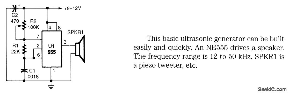
This basic ultrasonic generator can be built easily and quickly. An NE555 drives a speaker. The frequency range is 12 to 50 kHz. SPKRI is a piezo tweeter. The ultrasonic generator circuit utilizes the NE555 timer integrated circuit, which is...

This circuit is designed to charge between one and twelve NiCd cells using a car battery. With switch S1 set to the normal position, it is capable of charging up to six cells. The circuit operates by utilizing a car...
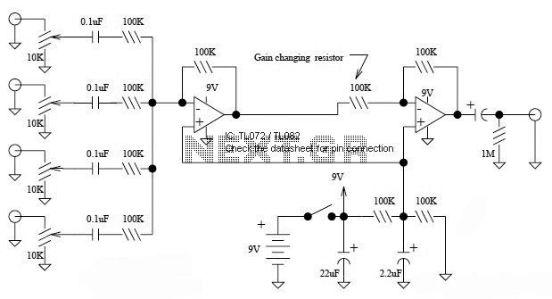
This is a simple mixer featuring four inputs and two operational amplifiers (op-amps). It is designed for mixing microphone signals or effects outputs. The overall gain from input to output is unity when the potentiometer associated with the input...
this circuit roughly doubles the voltage of the input, however the current output is low. doubled output is at V source. More: all resistors are 5 or 10 percent tolerance, 1/4-watt all capacitors are 10 percent tolerance. U1 NE555...