
Hidden wire detector

The circuit described is designed to safely detect the presence of electrical wiring before drilling, thereby preventing potential accidents. The core component, the CD4011 integrated circuit, is a dual 2-input NAND gate that can be configured to function as a signal processor for the detection mechanism. The inclusion of resistor R1, which should have a resistance greater than 50 Megohms, is critical for protecting the IC from high-voltage spikes that may occur during operation. This resistor acts as a buffer, ensuring that the sensitive IC does not get damaged by electrostatic discharges.
The antenna, made from a rigid copper wire, plays a pivotal role in the sensitivity of the device. The length of the antenna can be adjusted to optimize the detection range, allowing the device to effectively sense the electromagnetic fields generated by AC electrical wiring. When the antenna comes into proximity with such wiring, the induced electromagnetic field triggers the circuit to produce an audible signal, typically at a frequency of either 50 Hz or 60 Hz, depending on the local electrical supply frequency. This feature is particularly useful for identifying live wires in walls or ceilings.
In addition to the auditory alert, the device can also provide a visual indication through the use of LED VD1, as shown in Figure 2. The configuration of this more advanced circuit allows for simultaneous audio and visual feedback, enhancing the user's ability to detect wiring. The piezoelectric speaker HA1, connected to a bridge circuit, amplifies the sound output, ensuring that it is loud enough to be heard in various environments, even over background noise.
Overall, this device serves as an invaluable tool for anyone engaged in home improvement or construction, providing a reliable means of detecting hidden electrical wiring and preventing accidents associated with accidental drilling into live circuits.If you want to drill a hole in the wall then you must be sure that there`s no electrical wiring. This simple device. shown on the figure 1, can detect electrical wiring in the walls or ceiling. Resistor R1 protects IC CD4011 against electrostatic. A rigid copper piece of wire (~ 18 AWG, with length of 5. 15 cm) works as antenna. Sensitivity of the circuit depends on the length of the antenna. When the antenna is placed near the electrical wiring, then the circuit produces a sound with 50 or 60 Hz frequency. This device can detect broken wires in cables - near the broken wire the sound is off. The piezoelectric speaker HA1 is connected to the bridge circuit to achieve higher loudness. On the figure 2 is shown more complicated circuit, except audio it has visual indication based on LED VD1.
Resistance of the resistor R1 should be more than 50 Megohms. 🔗 External reference
Related Circuits

The circuit incorporates two oscillators, both operating at about 40kHz. The first, IC1a, is a standard CMOS oscillator with its frequency adjustable via VR1. The frequency of the second, IC1b, is highly dependent on the inductance of coil L1,...

With the help of a simple ceramic piezoelectric detector, it is possible to assemble an interesting and useful impact sensor unit, which can be used to detect... An impact sensor unit utilizing a ceramic piezoelectric detector operates by converting mechanical...

This unit uses one TSAL6100 IR/LED emitter from Digi-Key. This IR diode has a narrow (10 degree) radiation pattern at 940 NM. It is driven via 2n2904 transistor for maximum current pulses. The detector is a Vishay TSOP4838 38Khz...
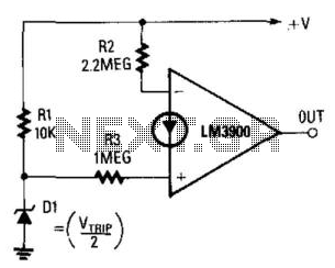
The output becomes high when the supply voltage drops below a threshold set by the zener diode D1. If D1 is a 5.6-V zener diode, the operational amplifier will activate when the supply voltage decreases to around 11 V....

This circuit employs a 15-kHz oscillator coil. When metal is removed from the energy field, the oscillator voltage is rectified and compared to a reference. A decrease in oscillator voltage activates comparator IC2, causing D4 (LED) to turn off. L1...

This is a false capture circuit or lie detector circuit. The basic principle is based on the resistance of human skin. While dry skin has a resistance of about 1 Megaohm. The lie detector circuit utilizes the principle of galvanic...