
Lie detector circuit

The lie detector circuit utilizes the principle of galvanic skin response (GSR), which measures the electrical resistance of the skin to determine psychological states. The circuit typically consists of a power supply, resistors, an operational amplifier, and a microcontroller or analog output to interpret the resistance values.
The resistance of human skin varies significantly based on moisture levels, emotional states, and other physiological factors. In a standard setup, electrodes are placed on the skin surface, usually on the fingers or palm. When a person is calm, the skin resistance is high, approximately 1 Megaohm for dry skin. However, during moments of stress or deception, the skin tends to become more conductive due to sweat gland activation, resulting in lower resistance readings.
The circuit is designed to convert the varying resistance into a measurable voltage signal. This is often achieved by using a voltage divider configuration where the skin resistance is one of the resistors in the divider. The output voltage, which correlates with the skin resistance, is then fed into an operational amplifier for amplification and further processing.
The microcontroller can be programmed to analyze the output signal and determine thresholds that indicate significant changes in skin resistance. These thresholds can be calibrated based on test subjects to enhance accuracy. The final output can be displayed on an LED indicator or sent to a computer for more detailed analysis.
In summary, the lie detector circuit is a practical application of electronic components to measure physiological responses, providing insight into human emotional states based on skin resistance variations.This is a false capture circuit or Lie detector circuit. The basic principle of the resistance of human skin. While dry skin is a resistance of about 1 Mega ohm.. 🔗 External reference
Related Circuits

Implementing peak-detector circuits is straightforward with the CA3130, as illustrated in the schematic diagram of this circuit. The figure below presents the schematic diagram. The CA3130 is a high-performance operational amplifier that is well-suited for peak detection applications due to...
This is a 25-watt basic power amplifier designed for ease of construction at a reasonable cost. It offers superior performance compared to standard STK module amplifiers commonly found in most mass-market stereo receivers produced today. The 25-watt basic power amplifier...

MSP430 microcontroller and I2C-compatible slave peripheral device. Temperature measurement tasks can be accomplished in a variety of ways. The MSP430 microcontroller is a low-power, 16-bit device widely used in embedded systems, particularly for applications requiring efficient power management and precise...
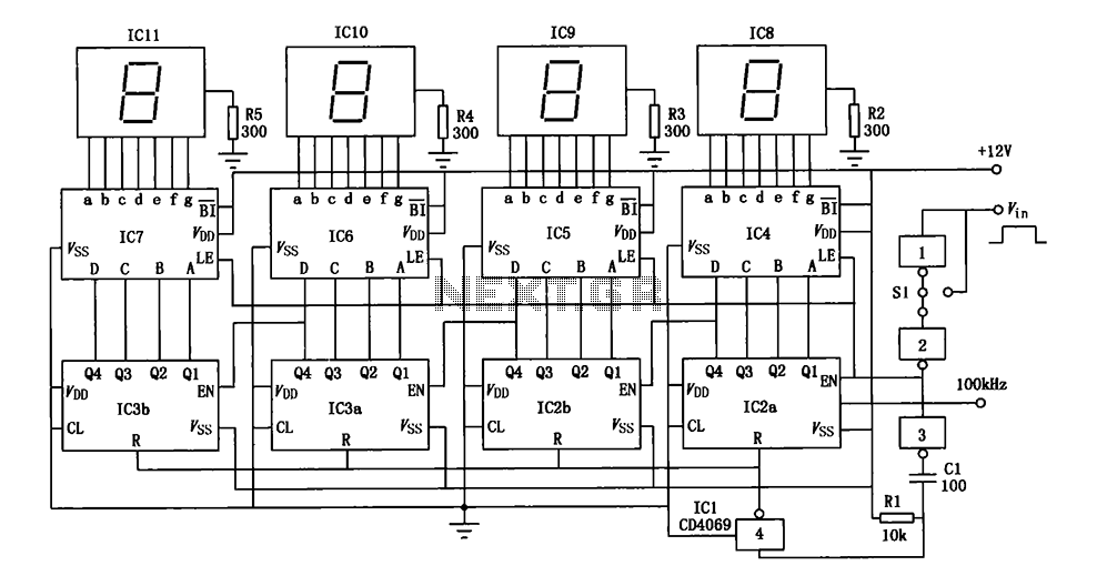
A digital pulse width measurement circuit is presented. It operates with a 100 kHz reference frequency to count the pulse width of the input signal. The count value represents the measured pulse width displayed on four seven-segment LED displays....
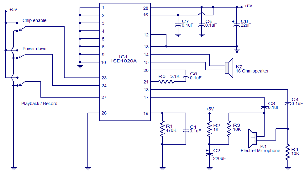
This circuit is designed in response to a request made by Mr. Vignesh for a voice recording and playback system. The circuit utilizes the ISD1020A IC from ISD, which is a CMOS single-chip record/playback device capable of recording voice...

The following circuit illustrates a simple 100W inverter circuit diagram. This circuit is based on the CD4047 integrated circuit (IC). Features include low power CMOS technology. The simple 100W inverter circuit utilizes the CD4047 IC, which is a versatile device...