
Vibration Sensor/Detector Circuit

An impact sensor unit utilizing a ceramic piezoelectric detector operates by converting mechanical stress from an impact into an electrical signal. The ceramic piezoelectric material generates a voltage when subjected to deformation, making it an effective choice for detecting impacts in various applications.
The circuit typically consists of the piezoelectric sensor connected in parallel with a resistor to form a voltage divider. This configuration allows for the monitoring of the voltage generated by the sensor when an impact occurs. The output can be further processed by an operational amplifier (op-amp) to enhance the signal strength, ensuring that even minor impacts can be detected.
For enhanced performance, a capacitor can be added in parallel with the resistor to filter out high-frequency noise, providing a cleaner signal. The output from the op-amp can be fed into a microcontroller or a comparator circuit, which can trigger an alert or perform an action based on the detected impact.
Power supply considerations are important; typically, a low-voltage DC supply is used to power the op-amp and any additional circuitry. The entire unit can be housed in a protective casing to ensure durability in various environments.
Applications for this impact sensor unit include monitoring structural integrity in buildings, detecting falls in elderly care systems, and providing security alerts in sensitive equipment. The simplicity and effectiveness of the piezoelectric impact sensor make it a valuable component in both commercial and industrial settings.With the help of a simple ceramic piezo-electric detector it is possible to assemble an interesting and useful Impact sensor unit,which can be used to dete.. 🔗 External reference
Related Circuits
A thermistor is utilized in the circuit for heat sensing, while two 5K variable resistors are incorporated to calibrate the circuit for activating the relay at the desired temperature. The inclusion of a 1N4007 diode across the relay serves...
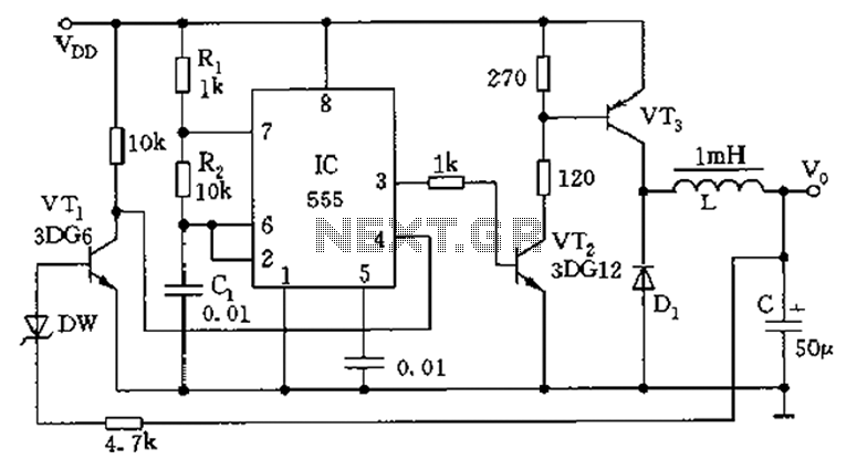
The circuit consists of a 555 timer configured as an astable multivibrator along with resistors R1 and R2 and capacitor C1. It generates an oscillation frequency of approximately 10 kHz with a duty cycle close to 50%. Transistors VT2...

This regulator is designed to control a DC generator. In this configuration, one side of the field is grounded. Diode D4 prevents the battery from discharging through the generator and serves as a replacement for the mechanical cut-out relay....
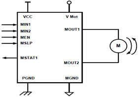
The schematic presented illustrates a 5A H-Bridge Module designed for the operation of a single Bipolar DC motor. The H-Bridge Module includes a header set (J2) and a connector terminal set (J1). Below is the pinout description for the...
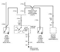
The following circuit illustrates the wiring diagram and electrical circuit troubleshooting for the 1997 Chevrolet Blazer. Features include a 4.3-liter Vortec V-6 engine, an AM-FM stereo radio with CD player, rear-wheel drive managed by a four-speed automatic transmission, air...
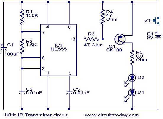
This circuit was designed in response to a request for a 1 kHz infrared (IR) transmitter circuit suitable for remote control applications. It is intended to serve as a low-power IR transmitter with an operating frequency of 1 kHz,...