
HiFI Headphone Amplifier
The CMoy headphone amplifier PCB design represents a compact and efficient solution for portable audio amplification. The integration of a bass-boost circuit enhances the listening experience by allowing users to tailor sound profiles to their preferences, particularly for low-frequency audio. The design's compatibility with various operational amplifiers provides flexibility in component selection, enabling users to customize performance characteristics based on specific audio requirements.
The implementation of a constant current charger for the 9V battery ensures that the amplifier remains powered during extended use, while the inclusion of blocking capacitors (C3+ and C3-) protects the op-amp from potential power supply fluctuations. The design's careful consideration of component placement, particularly the vertical orientation of resistors and diodes, maximizes space efficiency within the confined dimensions of the Altoids tin.
The use of a Rail Splitter (V1) to establish a virtual ground is critical for the proper functioning of the op-amp circuit, as it allows for balanced operation in a single-supply configuration. The high-quality blocking capacitor (C1) with low ESR contributes to improved audio fidelity by minimizing signal distortion.
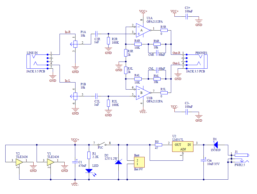
Overall, this PCB design not only meets functional requirements but also considers user experience through its compact form factor and customizable features, making it an excellent choice for audiophiles seeking portable amplification solutions.This is an article about my new PCB design for CMoy headphone amplifier. Main feature is that the new PCB fits exactly to the classic Altoids tin-can. This new CMoy incorporates moreover bass-boost circuit and constant current charger for 9V battery. P1 is the volume potentiometer with On/Off switch. C2 is coupling capacitor. R2 defines the input impedance of opamp. R3 and R4 define the gain of the amplifier (5x in this case). Rb and Cb form bass-boost circuit. These components increase the gain for low frequencies. For the low frequencies the gain is 14. By increasing the Rb resistors you can increase the gain for low frequencies and vice verse. You can decrease the cutting frequency by increasing the Cb capacitors. Bass-boost can be deactivated by shorting out Rb resistors. As a opamp I use OPA2132, but many others can be used as well like OPA2134, OPA2227, NE5532, . C3+ and C3- are blocking capacitors for power supply for opamp. R5 is optional, but to avoid some bouncing at the output the value should be around 22 ohms. V1 is a Rail Splitter which creates virtual ground. C1 is high quality blocking capacitor with low ESR. Resistor R1 limits the current through LED. The value should be modify according the type of LED. D2 limits the maximum voltage in the input to 12V. U2 together with resistor R0 create constant current source for charging the 9V battery. In my case the R0 has value 47 ohms and then the current is around 25mA. Cin is tantalum blocking capacitor for U2. D1 is Schottky diode for avoiding any damage when the voltage with opposite polarity is connected. I designed the PCB with two rounded corners. The PCB fits exactly to the Altoids tin (see pictures below). On the PCB are also nice pictures of input jack and headphones. The resistors and diodes must be assembled vertically to reduce occupied space. 🔗 External reference
Related Circuits
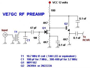
This is a simple VE7GC Popcorn RF preamplifier designed by Dick Pattinson. The circuit features a single tuned circuit at the input stage, allowing direct connection to a mixer or product detector in a straightforward receiver project. Adjustable RF...
The final amplifier serves as the power source for every audio installation. Its function is to transform a small alternating voltage into a robust signal suitable for driving loudspeakers. The final amplifier, often referred to as a power amplifier, plays...
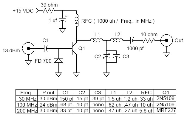
This is a universal 1 Watt RF class C amplifier that is ideally suited for low power FM transmitters. The input should be at least 100mW to achieve a 1W output. It is recommended to enclose the amplifier in...
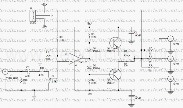
This circuit is useful to amplify and distribute video signals with low noise and without losses. The CA3100 is a fast opamp designed to amplify video signals. Set the P1 to control the input signal level to have a...
The provided description pertains to an operational amplifier (opamp) of medium power, specifically configured to amplify headphone signals and drive low loads. The opamp essentially comprises two amplifiers. The voltage gain for each amplifier is set at 40dB, determined by...
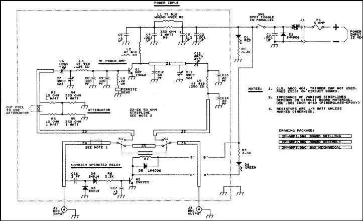
This article discusses a 2-meter amplifier capable of delivering an output of 25-30 watts. Over 35 units have been acquired at a cost of less than $50 each in bulk. Photo A displays the final version of the circuit...