
Headphone amplifier with TDA2004
The bandwidth restriction for each unit is regulated by the combination of specific components. For instance, the combination of resistor R12 and capacitor C2, as well as resistor R13 and capacitor C15, is responsible for limiting the frequency response to 22KHz. This frequency cap ensures that the amplifier remains stable and does not oscillate at high frequencies, which could potentially damage the connected headphones.
Furthermore, resistors R5 and R10 play a crucial role in impedance matching. These resistors help adapt the impedance of the earphones, ensuring optimal power transfer from the amplifier to the earphones. Impedance matching is particularly important in this context as it prevents signal loss and distortion, thereby improving the overall sound quality.
In summary, this medium-power operational amplifier has been designed with a focus on headphone amplification, featuring a dual-amplifier setup, a voltage gain of 40dB per channel, a bandwidth limit of 22KHz, and dedicated components for impedance matching.A opamp. medium power, here its used as amplifier of headphones with possibility drive low loads. It contains in a nutshell two amplifiers. The voltage gain, has been determined in 40dB, from the R3-4 and R11-12, for each channel, respectively. The restriction of bandwidth for each unit is regulated by the combination of R12, C2 and R13, C15, in 22KHZ.
The R5, R10 attend to the adaptation of impedance earphones. 🔗 External reference
Related Circuits
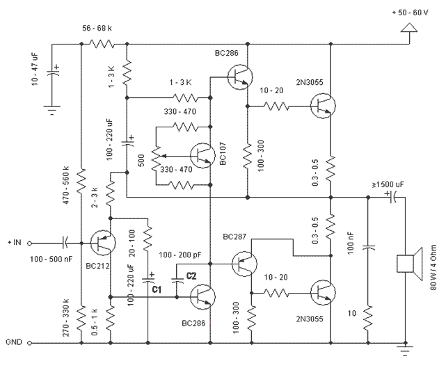
This is a simple and low cost 60W power amplifier. The optimal supply voltage is around 50V, but this amp can work from 30 to 60V. The maximum input voltage is around 0.8 - 1V. As you can see,...
Here I propose a project of an AB class power amplifier, at its simplest, assembled with common components (not very expensive), based on traditional diagrams: a symmetrical differential input stage, a cascode stage driver, and a MOSFET output stage....
A 2 x 18W Hi-Fi Stereo Power Amplifier is designed using two TDA2030 integrated circuits (ICs). This amplifier features excellent input sensitivity, low distortion levels, stable operation, and comprehensive protection against overloads and output short circuits. It can serve...

A compact audio amplifier circuit utilizing the TDA 7052 integrated circuit from Philips. This circuit is suitable for use as a pocket radio amplifier, delivering an output power of 2 watts. The TDA 7052 is a low-voltage audio amplifier designed...
Blue VALUES replaced by values in RED. Blue COMPONENTS removed from circuit. Red components added to circuit. More: Optional: move relay mute contacts to other side of C21. The provided description indicates modifications to an existing electronic circuit. The changes...
This is a schematic diagram of a video amplifier circuit with bi-phase output. The bi-phase output generates both positive-going and negative-going signals, enabling balanced signaling. The primary component of this circuit is the LM1201. In this configuration, the inverted...