
HiFi Pre$2damp circuit diagram
The HiFi pre-amplifier circuit is designed to amplify weak audio signals while maintaining high fidelity and low noise levels. The circuit typically consists of several key components, including operational amplifiers (op-amps), resistors, capacitors, and possibly a power supply circuit.
The operational amplifiers serve as the core amplification element, configured in a non-inverting or inverting mode depending on the desired gain and input/output characteristics. The choice of op-amps is crucial, as low-noise types are preferred to minimize unwanted noise in the output signal.
Resistors are used to set the gain of the amplifier and to provide feedback within the circuit. The values of these resistors can be adjusted to achieve the desired amplification level, ensuring that the output signal matches the requirements of downstream audio equipment.
Capacitors play a vital role in coupling and decoupling stages of the circuit. They block DC components while allowing AC signals to pass, which is essential for audio applications. Additionally, capacitors are used for filtering purposes, helping to smooth out fluctuations in the power supply and reducing noise.
The frequency response of the pre-amplifier is critical for achieving optimal audio performance. A range from 10 Hz to 100 kHz allows for the reproduction of low bass notes as well as high-frequency details, ensuring a full and rich sound experience. Careful selection of component values and circuit layout can help maintain this wide frequency response while minimizing distortion and phase shift.
In summary, the HiFi pre-amplifier circuit is engineered to provide high-quality audio amplification with low noise and a broad frequency range, making it suitable for various audio applications. Proper design and component selection are essential to ensure that the pre-amplifier meets the high standards expected in modern audio systems.This is a HiFi pre-amplifiercircuit diagramwith low noise output. Very wide range frequency from about 10Hz until up to 100Khz will be gained by this preamplifier for maximumaudioperformance. 🔗 External reference
Related Circuits
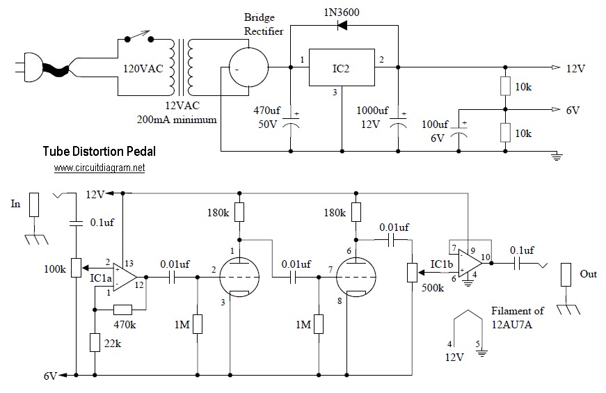
Tube distortion pedal circuit diagram. IC1: 747 dual op-amp; other ICs may be substituted, but the pinout will differ, so the datasheet should be checked. IC2: LM340K-12V voltage regulator. All resistors are 1/2 W. The bridge rectifier is a...
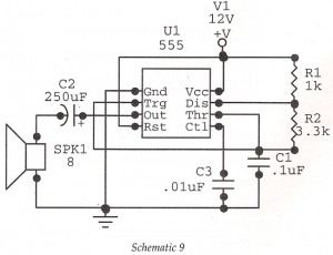
This circuit features an astable oscillator constructed around a 555 timer, generating an alarm tone of 1.8 kHz, which directly drives a speaker. It serves as a fundamental alarm circuit that can be utilized in various projects. Although the...
Assortment of siren circuits. This month, three different types of siren circuits are being created based on the 555 timer. The first circuit simulates the siren of a British police car. It utilizes two 555 timers. The design of the...
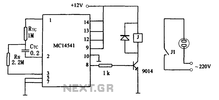
The circuit illustrated in FIG MC14541 is a straightforward timing circuit utilizing the MC14541 integrated circuit (IC). By adjusting the parameter map, the timing can be set for a duration of 3 hours, with options to select various RTC,...
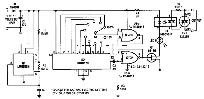
A timer (LM555CN) and decode counter are utilized to generate duty cycles ranging from 10% to 100% for controlling the operational time of a heating system. V2 operates as a decode counter that can be adjusted for duty cycles...

The circuit is a high-power car audio amplifier schematic. It functions as a car audio amplifier using the PA02 and LH0101 integrated circuits (ICs). Each IC delivers an output power of 30W with an 8-ohm impedance. The part list...