
Simple timer circuit MC14541

The MC14541 timing circuit is designed to provide precise timing functions for various applications. It operates by employing a combination of resistors (Rs), capacitors, and the integrated circuit itself to generate a stable time delay. The choice of RTC (Real-Time Clock) and CTC (Clock Time Constant) values plays a critical role in defining the timing characteristics of the circuit.
In this circuit, the MC14541 IC serves as the core timing element, which is capable of producing accurate delays through its internal architecture. The timing duration can be set to 3 hours, making it suitable for applications that require long-term timing operations. Adjustments to the parameter map allow for flexibility in timing configurations, which can be tailored to specific requirements.
The selection of resistor and capacitor values influences the timing intervals significantly. For instance, a higher resistance value in conjunction with a larger capacitor will extend the timing duration, while lower values will shorten it. This adaptability enables the circuit to be utilized in various scenarios, from simple timing tasks to more complex applications where precise timing is essential.
Overall, the MC14541 timing circuit is an efficient solution for implementing timing functions, providing versatility through its adjustable parameters and the ability to customize timing durations according to user needs. As shown in FIG MC14541 constituted by a simple timing circuit. The circuit uses IC MC14541 constitute a simple timing circuit. Press the parameter map, the timing for 3 hours, and can choose different RTC, CTC and Rs values. In order to achieve the desired timing control.
Related Circuits
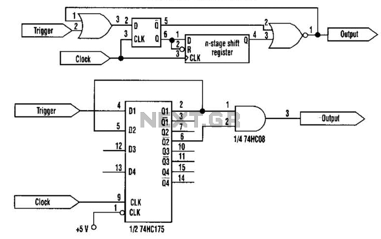
This approach utilizes a Hip-Hop, a shift register, and two gates (A). Before the one-shot pulse, the output of the NOR gate is 0. Consequently, the data input of the D-type flip-flop is equivalent to the trigger. When a...
Feedback in a public address amplifier should be avoided. The ideal solution is to adjust the positions of the microphone and speaker; however, this is not always feasible in many situations. A frequency shifter that alters the output frequency...
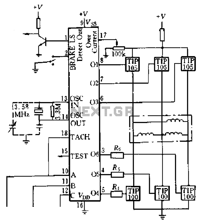
Four application examples are presented in the figure, focusing on a three-phase brushless DC motor used in Winchester disk drives with an operating speed of 3600 RPM. Although the original design specifies an operating speed of 3600 RPM, alternative...
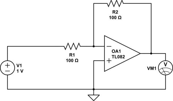
Considering a simple circuit as illustrated below, when the voltage source activates suddenly (changing from 0V to 1V), current will flow through the resistor R1. Assuming an ideal operational amplifier (op-amp) that draws no current, and an ideal voltmeter...
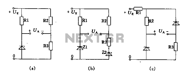
The circuit depicted in Figures A, B, and C demonstrates a high voltage coefficient. When the regulator resistance \( r_z \) is held constant, the bridge configuration achieves an infinite voltage coefficient. In Figure A, the load circuit is...
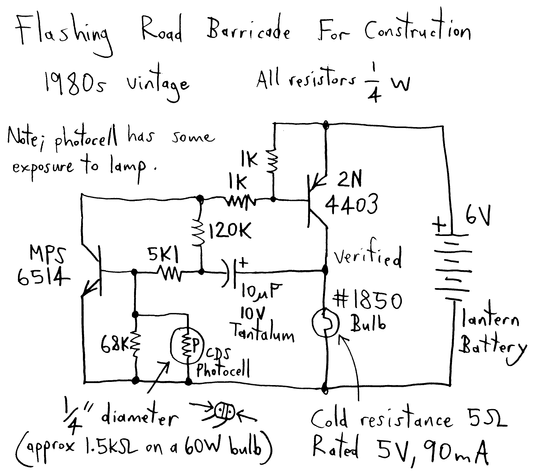
A well-designed circuit that automatically turns off if the pushbutton is held down or jammed for an extended period. It is not re-triggerable while the light remains on. The circuit initially starts at full brightness and gradually dims to...